Micrologic™ 2.0A, 3.0A, 5.0A, and 6.0A Electronic Trip Units | |
Rev. 01, 07/2012 | Section |
|
|
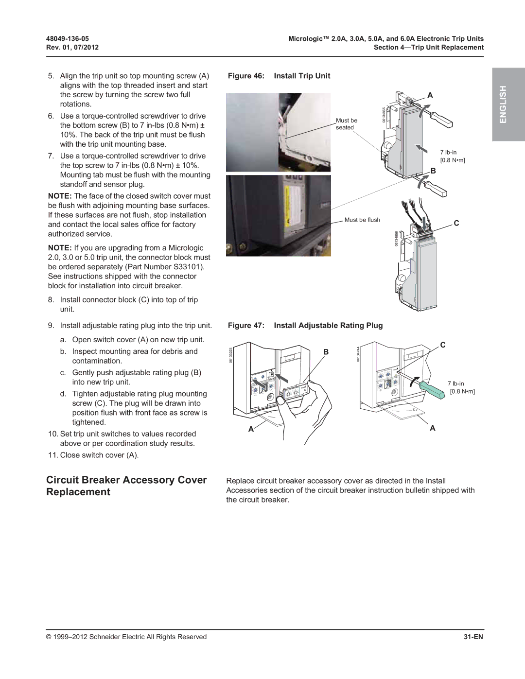
5.Align the trip unit so top mounting screw (A) aligns with the top threaded insert and start the screw by turning the screw two full rotations.
6.Use a
7.Use a
Figure 46: Install Trip Unit
Must be seated
A
06134855![]()
![]()
![]()
![]()
![]()
![]()
7
[0.8 N•m]
B
ENGLISH
NOTE: The face of the closed switch cover must be flush with adjoining mounting base surfaces. If these surfaces are not flush, stop installation and contact the local sales office for factory authorized service.
NOTE: If you are upgrading from a Micrologic 2.0, 3.0 or 5.0 trip unit, the connector block must be ordered separately (Part Number S33101). See instructions shipped with the connector block for installation into circuit breaker.
8.Install connector block (C) into top of trip unit.
9.Install adjustable rating plug into the trip unit.
a.Open switch cover (A) on new trip unit.
b.Inspect mounting area for debris and contamination.
c.Gently push adjustable rating plug (B) into new trip unit.
d.Tighten adjustable rating plug mounting screw (C). The plug will be drawn into position flush with front face as screw is tightened.
10.Set trip unit switches to values recorded above or per coordination study results.
11.Close switch cover (A).
 Must be flush
06134856
Figure 47: Install Adjustable Rating Plug
06133223 | B | 06134244 |
|
|
alarm
|
|
|
|
|
|
|
|
|
|
|
|
|
|
|
| long time | tr | 4 | 8 |
| 12 |
|
|
|
| ||
|
|
|
|
|
|
|
|
|
|
|
|
|
|
| Ir |
| .8 | .9 | (s) |
|
| 16 |
|
|
|
| |
|
|
|
|
|
|
|
|
|
|
|
|
|
|
| .7 |
| 2 |
|
|
| 20 |
|
|
|
| ||
|
|
|
|
|
|
|
|
|
|
|
|
|
|
| .6 |
| .95 | 1 |
|
|
| 24 |
|
|
|
| |
|
|
|
|
|
|
|
|
|
|
|
|
|
|
|
| .98 |
| .5 | @ | 6 Ir | instantan | eous | |||||
|
|
|
|
|
|
|
|
|
|
|
|
|
|
| .5 | x In | 1 |
|
|
|
|
| |||||
|
|
|
|
|
| instantaneous |
|
|
|
|
|
|
| .4 |
|
|
|
|
|
| I i | 4 | 5 |
| |||
|
|
|
|
|
|
|
|
|
|
|
|
| short time | tsd | .4 | .4 | .3.2 | 2.53 |
|
| 86 | ||||||
|
|
|
|
|
| I i | 4 | 5 |
|
|
|
|
|
| Isd | 4 | 5 | .3 |
|
| .1 | 2 |
| 10 | |||
shor | t ti | e | t |
| 3 |
| 6 |
|
|
|
|
|
|
| 3 |
| 6 | .2.1 |
|
| 1.5 | x In | |||||
|
| .2 | 2.5 |
| 8 |
|
|
|
|
|
| 2.5 |
| 8 | I | t | 0 |
|
|
| |||||||
Isd | 4 | 56 | .3 | .1 | 2 |
| 10 |
|
|
|
|
|
| alarm | 2 |
| 10 | on |
|
|
|
|
| ||||
3 |
| 1.5 x In |
|
|
|
|
|
|
| 1.5 |
| delay |
|
|
|
|
| ||||||||||
2.5 |
|
|
| .2 | 0 |
| long time | tr |
| 8 | 12 |
| x Irg |
|
|
|
|
|
|
|
|
| |||||
2 |
|
| 8 | .1 | I2t |
|
| test | Ir | .8 | .9 | (s) | 4 |
| 16 | settin |
|
|
|
|
|
|
|
|
|
| |
1.5 |
| 10 | on | delay |
|
|
| .7 |
| .95 | 2 |
|
| 20 |
|
|
|
|
|
|
|
|
|
|
|
| |
| x Ir |
|
|
|
|
|
| .6 |
| .98 | 1 |
|
| 24 |
|
|
|
|
|
|
|
|
|
|
|
| |
setting |
|
|
|
|
|
| .5 |
| 1 |
| .5 | @ 6 Ir |
|
|
|
|
|
|
|
|
|
|
|
| |||
|
|
|
|
|
|
|
|
| .4 | x In |
|
|
|
|
|
|
|
|
|
|
|
|
|
|
|
|
|
A
C
C
7
[0.8 N•m]
A
Circuit Breaker Accessory Cover | Replace circuit breaker accessory cover as directed in the Install |
Replacement | Accessories section of the circuit breaker instruction bulletin shipped with |
| the circuit breaker. |
© |
|
