Compact® NSF and NSJ 150 to 600 A Circuit Breakers
Section
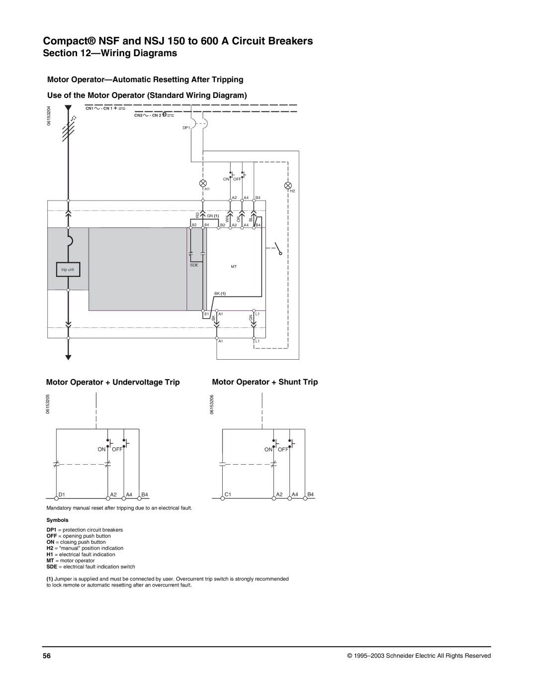
Motor
Use of the Motor Operator (Standard Wiring Diagram)
06153204 | CN1 - CN 1 | + |
|
| CN2 - CN 2 Ð |
DP1
ON OFF
H1
A2 | A4 |
H2
B4
RD | GN (1) |
82 | 84 |
WH
B2
OR
A2
BL
A4
B4
trip unit |
SDE | MT |
BK (1)
81
BK
A1
GN
L1
A1L1
Motor Operator + Undervoltage Trip | Motor Operator + Shunt Trip |
06153205
06153206
ON |
|
|
|
|
|
|
|
|
|
|
| OFF |
|
|
| ON |
| OFF | |||
|
|
| ||||||||
|
|
|
|
|
|
|
|
|
|
|
D1 | A2 | A4 | B4 |
| C1 | A2 | A4 | B4 |
Mandatory manual reset after tripping due to an electrical fault.
Symbols
DP1 = protection circuit breakers
OFF = opening push button
ON = closing push button
H2 = "manual" position indication
H1 = electrical fault indication
MT = motor operator
SDE = electrical fault indication switch
(1)Jumper is supplied and must be connected by user. Overcurrent trip switch is strongly recommended to lock remote or automatic resetting after an overcurrent fault.
56 | © |