Compact® NSF and NSJ 150 to 600 A Circuit Breakers
Section
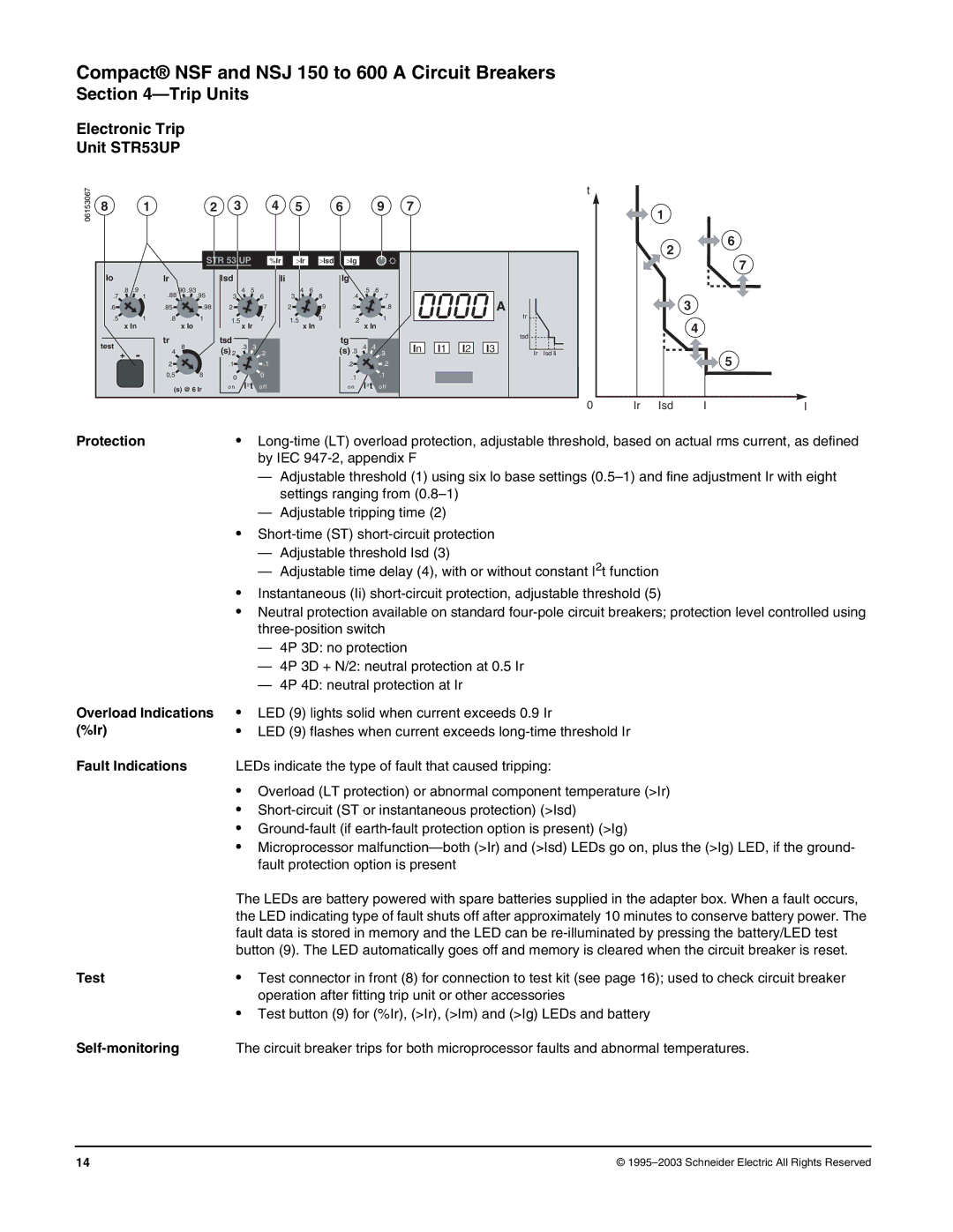
Electronic Trip
Unit STR53UP
06153067
81
2 | 3 | 4 | 5 | 6 | 9 |
STR 53 UP |
| > | > | > | |
t
7
1
2
6
%Ir | Ir Isd Ig |
7
Io
.8 .9
.7 1
.6
.5 1
x In
test
+-
Ir
.88.90 .93 | .95 |
.85 | .98 |
.8 | 1 |
x Io
tr | 8 | |
4 | ||
| ||
2 |
| |
0,5 | 8 |
(s) @ 6 Ir
Isd
4 5
36
2 ![]() 7
7
1.57
x Ir
tsd | .3 .3 |
| |
(s).2 | .2 | ||
| |||
.1 |
| .1 | |
0 |
| 0 | |
o n | I2 t | o ff |
Ii
4 | 6 |
3 | 8 |
2 | 9 |
1.5 | 9 |
x In
Ig
.5 | .6 |
.4 | .7 |
.3 | .8 |
.2 | 1 |
x In
tg | .4 .4 |
|
(s) .3 | .3 | |
.2 |
| .2 |
.1 |
| .1 |
I2 t |
| |
o n | o ff |
|
|
|
| A |
|
|
|
|
| tr |
|
|
|
|
| tsd |
|
In | I1 | I2 | I3 | Ir | Isd li |
|
|
|
|
3
![]() 4
4
5
0
Ir | Isd | I | I |
Protection | • | ||
| by IEC | ||
| — Adjustable threshold (1) using six lo base settings | ||
|
| settings ranging from | |
| — Adjustable tripping time (2) | ||
| • | ||
| — Adjustable threshold Isd (3) | ||
| — Adjustable time delay (4), with or without constant I2t function | ||
| • Instantaneous (Ii) | ||
| • Neutral protection available on standard | ||
| |||
| — | 4P | 3D: no protection |
| — | 4P | 3D + N/2: neutral protection at 0.5 Ir |
| — | 4P | 4D: neutral protection at Ir |
Overload Indications (%Ir)
Fault Indications
•LED (9) lights solid when current exceeds 0.9 Ir
•LED (9) flashes when current exceeds
LEDs indicate the type of fault that caused tripping:
•Overload (LT protection) or abnormal component temperature (>Ir)
•
•
•Microprocessor
The LEDs are battery powered with spare batteries supplied in the adapter box. When a fault occurs, the LED indicating type of fault shuts off after approximately 10 minutes to conserve battery power. The fault data is stored in memory and the LED can be
Test | • | Test connector in front (8) for connection to test kit (see page 16); used to check circuit breaker |
|
| operation after fitting trip unit or other accessories |
| • | Test button (9) for (%Ir), (>Ir), (>Im) and (>Ig) LEDs and battery |
| The circuit breaker trips for both microprocessor faults and abnormal temperatures. | |
14 | © |