Compact® NSF and NSJ 150 to 600 A Circuit Breakers
Section
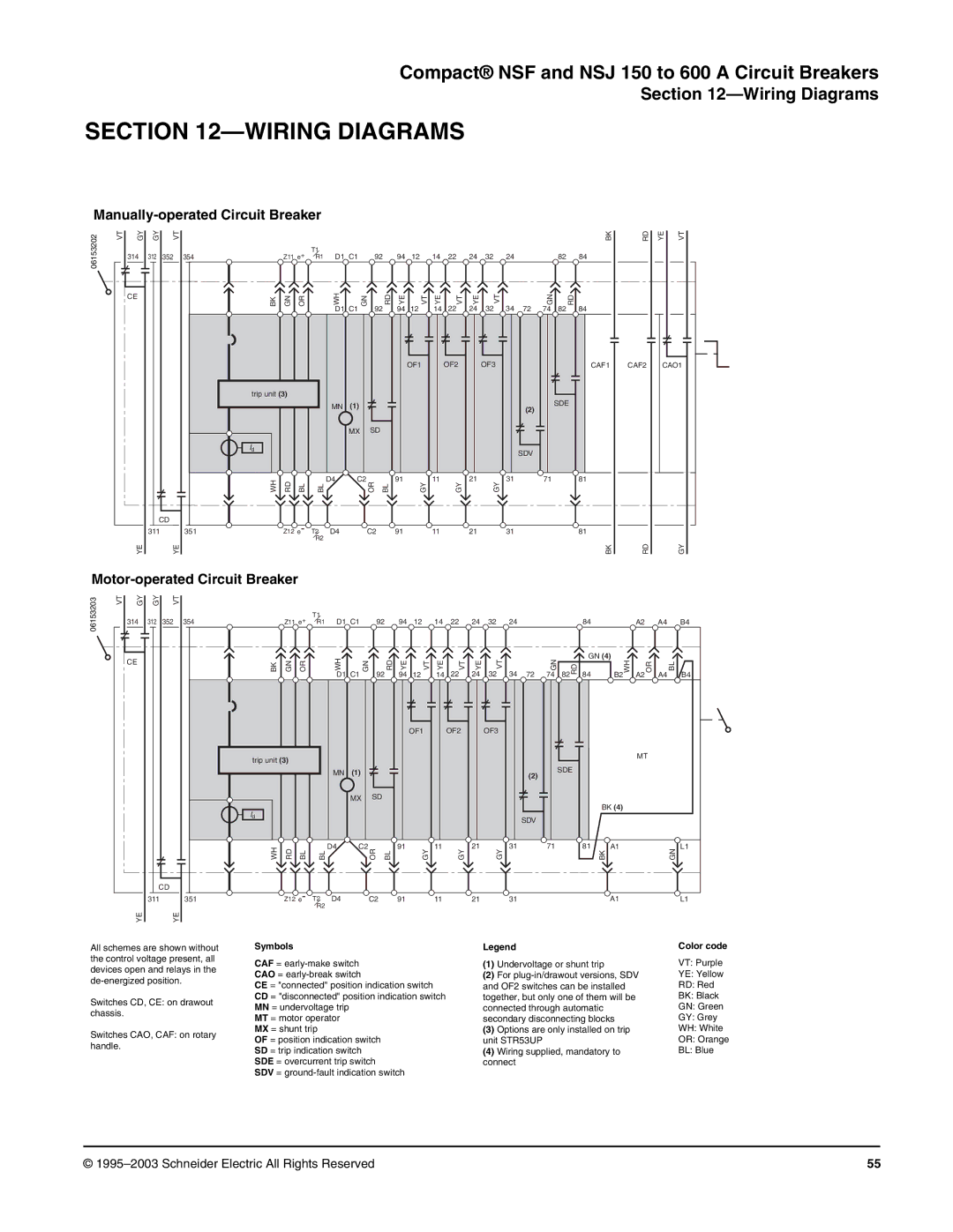
SECTION 12—WIRING DIAGRAMS
Manually-operated Circuit Breaker
06153202 | VT |
GY
314
CE
YE
GY |
| VT | |
312 |
| 352 | |
|
|
|
|
CD
311
YE
|
|
|
|
|
|
|
|
|
|
|
|
|
|
|
|
|
| BK | RD | YE | VT |
354 | Z11 e+ | T1 | D1 C1 | 92 |
| 94 | 12 | 14 | 22 | 24 | 32 | 24 |
|
| 82 | 84 |
|
|
| ||
R1 |
|
|
|
|
|
| |||||||||||||||
BK | GN | OR |
| WH | GN | 92 | RD | YE | VT | YE | VT | YE | VT | 34 | 72 | GN | 82 | RD |
|
|
|
|
|
|
| D1 C1 |
| 94 | 12 | 14 | 22 | 24 | 32 | 74 | 84 |
|
|
| |||||
|
|
|
|
|
|
|
|
| OF1 |
| OF2 |
| OF3 |
|
|
|
| CAF1 | CAF2 | CAO1 | |
trip unit (3) |
|
|
|
|
|
|
|
|
|
|
|
|
|
|
|
|
|
|
|
| |
|
|
|
| MN | (1) |
|
|
|
|
|
|
|
|
| (2) |
| SDE |
|
|
| |
|
|
|
|
|
|
|
|
|
|
|
|
|
|
|
|
|
|
| |||
|
|
|
|
|
|
|
|
|
|
|
|
|
|
|
|
|
|
|
|
| |
|
|
|
|
| MX | SD |
|
|
|
|
|
|
|
|
|
|
|
|
|
|
|
Id |
|
|
|
|
|
|
|
|
|
|
|
|
|
| SDV |
|
|
|
|
|
|
|
|
|
|
|
|
|
|
|
|
|
|
|
|
|
|
|
|
|
|
| |
WH | RD | BL | BL | D4 | C2 | OR | BL | 91 | GY | 11 | GY | 21 | GY | 31 |
| 71 |
| 81 |
|
|
|
|
|
|
|
|
|
|
|
|
|
|
|
| |||||||||
351 | Z12 e- | T2 | D4 |
| C2 |
| 91 |
| 11 |
| 21 |
| 31 |
|
|
| 81 |
|
|
| |
|
|
| R2 |
|
|
|
|
|
|
|
|
|
|
|
|
|
|
|
|
|
|
|
|
|
|
|
|
|
|
|
|
|
|
|
|
|
|
|
| BK | RD |
| GY |
Motor-operated Circuit Breaker
06153203 | VT |
GY
314
CE
YE
GY |
| VT | |
312 |
| 352 | |
|
|
|
|
CD
311
YE
354 | Z11 e+ | T1 | D1 C1 | 92 |
| 94 | 12 | 14 | 22 | 24 | 32 | 24 |
|
|
|
| 84 |
|
| A2 |
| A4 | B4 | ||
R1 |
|
|
|
|
|
|
|
| |||||||||||||||||
| GN | OR |
| WH | GN |
| RD | YE | VT | YE | VT | YE | VT |
|
| GN |
|
| GN (4) | WH |
| OR |
| BL | |
BK |
| 92 | 34 | 72 | 82 | RD | 84 | B2 | A2 | A4 | |||||||||||||||
|
|
|
| D1 | C1 |
| 94 | 12 | 14 | 22 | 24 | 32 | 74 |
|
|
| B4 | ||||||||
|
|
|
|
|
|
|
|
| OF1 |
| OF2 |
| OF3 |
|
|
|
|
|
|
|
|
|
|
|
|
trip unit (3) |
|
|
|
|
|
|
|
|
|
|
|
|
|
|
|
|
|
|
|
| MT |
|
| ||
|
|
|
|
|
|
|
|
|
|
|
|
|
|
|
|
|
|
|
|
|
|
|
| ||
|
|
|
| MN | (1) |
|
|
|
|
|
|
|
|
| (2) |
| SDE |
|
|
|
|
|
|
| |
|
|
|
|
|
|
|
|
|
|
|
|
|
|
|
|
|
|
|
|
|
|
| |||
|
|
|
|
|
|
|
|
|
|
|
|
|
|
|
|
|
|
|
|
|
|
|
|
| |
|
|
|
|
| MX | SD |
|
|
|
|
|
|
|
|
|
|
|
|
|
|
|
|
|
|
|
Id |
|
|
|
|
|
|
|
|
|
|
|
|
|
|
|
|
|
|
| BK (4) |
|
|
|
|
|
|
|
|
|
|
|
|
|
|
|
|
|
|
| SDV |
|
|
|
|
|
|
|
|
|
| |
|
|
|
|
|
|
|
|
|
|
|
|
|
|
|
|
|
|
|
|
|
|
|
|
| |
WH | RD |
|
| D4 | C2 | OR |
| 91 | GY | 11 | GY | 21 | GY | 31 |
| 71 |
|
| 81 | A1 |
|
|
|
| L1 |
BL | BL |
|
| BL |
|
|
|
|
|
|
|
|
| BK |
|
|
|
| GN | ||||||
351 | Z12 e- | T2 | D4 |
| C2 |
| 91 |
| 11 |
| 21 |
| 31 |
|
|
|
|
| A1 |
|
|
|
| L1 | |
|
|
| R2 |
|
|
|
|
|
|
|
|
|
|
|
|
|
|
|
|
|
|
|
|
|
|
All schemes are shown without the control voltage present, all devices open and relays in the
Switches CD, CE: on drawout chassis.
Switches CAO, CAF: on rotary handle.
Symbols
CAF =
CE = "connected" position indication switch CD = "disconnected" position indication switch MN = undervoltage trip
MT = motor operator MX = shunt trip
OF = position indication switch SD = trip indication switch SDE = overcurrent trip switch
SDV =
Legend
(1)Undervoltage or shunt trip
(2)For
(3)Options are only installed on trip unit STR53UP
(4)Wiring supplied, mandatory to connect
Color code
VT: Purple
YE: Yellow
RD: Red
BK: Black
GN: Green
GY: Grey
WH: White
OR: Orange
BL: Blue
© | 55 |