description/installation
linear feedback connection
h1000 pilot
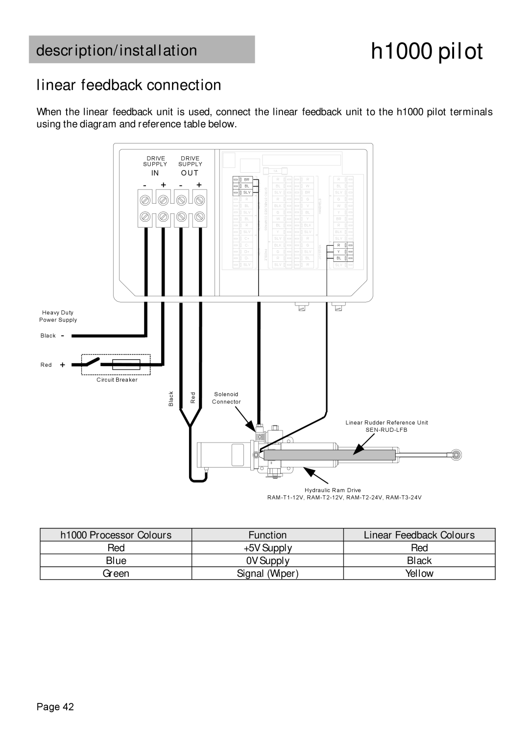
When the linear feedback unit is used, connect the linear feedback unit to the h1000 pilot terminals using the diagram and reference table below.
DRIVE DRIVE SUPPLY SUPPLY
IN OUT
- + - +
BR |
BL |
SLV |
R |
BL |
SLV |
BL |
R |
SLV |
C+ |
C- |
D+ |
D- |
SLV |
![]() AD10ALARM M O B CLUTCH
AD10ALARM M O B CLUTCH
1A |
| R | |
GYRO- | BL | |
SLV | ||
| ||
STABILISED | R | |
G | ||
COMPASS | BLK | |
W | ||
| BL | |
| Y | |
| SLV | |
PADDLE | BLK | |
R | ||
| G | |
| SLV |
R |
W |
BR |
G |
V |
BL |
Y |
BLK |
SLV |
R |
G |
SLV |
BL |
R |
![]() JOYSTICKHANDHELD
JOYSTICKHANDHELD
RUDDER![]()
R |
BL |
SLV |
G |
W |
Y |
BR |
R |
BLK |
SLV |
R |
Y |
BL |
SLV |
Heavy Duty
Power Supply
Black -
Red +
Circuit Breaker
Black
Red
Solenoid
Connector
Linear Rudder Reference Unit |
Hydraulic Ram Drive
h1000 Processor Colours | Function | Linear Feedback Colours |
Red | +5V Supply | Red |
Blue | 0V Supply | Black |
Green | Signal (Wiper) | Yellow |
Page 42