description/installation
continuous drive unit connections
h1000 pilot
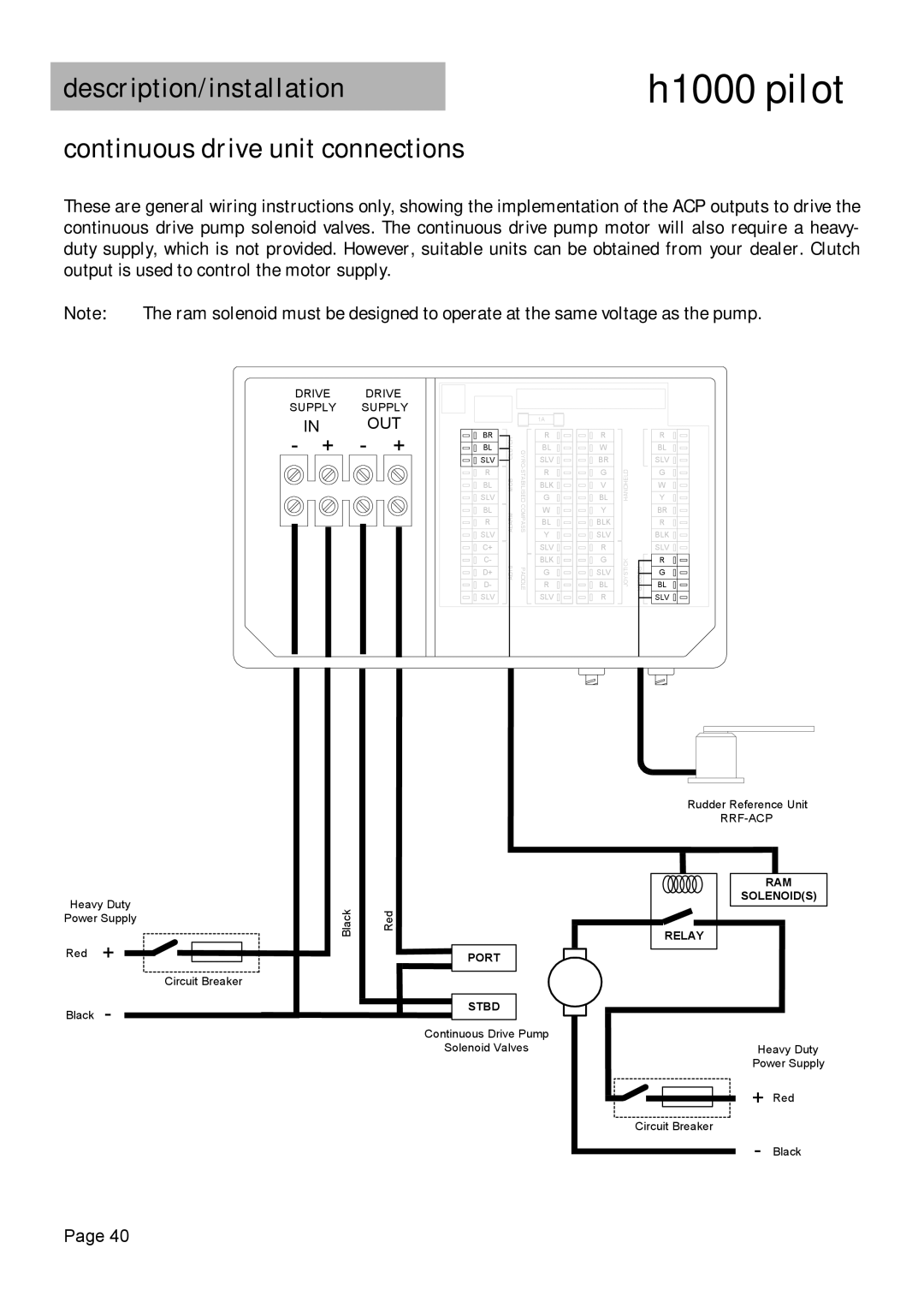
These are general wiring instructions only, showing the implementation of the ACP outputs to drive the continuous drive pump solenoid valves. The continuous drive pump motor will also require a heavy- duty supply, which is not provided. However, suitable units can be obtained from your dealer. Clutch output is used to control the motor supply.
Note: The ram solenoid must be designed to operate at the same voltage as the pump.
DRIVE DRIVE
SUPPLY SUPPLY
IN OUT
- + - +
BR |
BL |
SLV |
R |
BL |
SLV |
BL |
R |
SLV |
C+ |
C- |
D+ |
D- |
SLV |
![]() AD10ALARM MOB CLUTCH
AD10ALARM MOB CLUTCH
1A |
| R | |
GYRO | BL | |
SLV | ||
| ||
R | ||
G | ||
COMPASS | BLK | |
W | ||
| ||
| BL | |
| Y | |
| SLV | |
PADDLE | BLK | |
R | ||
| G | |
| SLV |
R |
W |
BR |
G |
V |
BL |
Y |
BLK |
SLV |
R |
G |
SLV |
BL |
R |
![]() JOYSTICKHANDHELD
JOYSTICKHANDHELD
RUDDER![]()
R |
BL |
SLV |
G |
W |
Y |
BR |
R |
BLK |
SLV |
R |
G |
BL |
SLV |
Heavy Duty | Black | |
Power Supply | ||
|
| |
Red | + |
|
|
| Circuit Breaker |
Black | - |
|
Red
PORT
STBD
Continuous Drive Pump
Solenoid Valves
Rudder Reference Unit
RAM
SOLENOID(S)
RELAY
Heavy Duty
Power Supply
+ Red
Circuit Breaker
- Black
Page 40
