CHAPTER 7 Wireless Configuration
Wireless Distribution System (WDS)
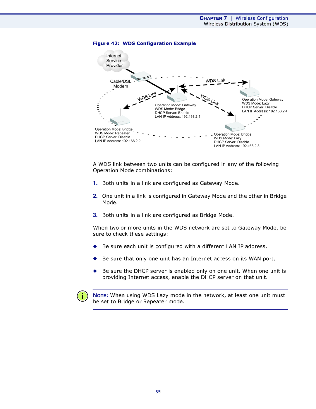
Figure 42: WDS Configuration Example
Internet |
|
|
|
| ||
Service |
|
|
|
| ||
Provider |
|
|
|
| ||
|
|
|
| WDS | Link | |
| Cable/DSL |
|
| |||
|
|
|
| |||
| Modem |
|
|
|
|
|
|
|
| Link | WDS |
|
|
|
| WDS |
| Link | ||
|
|
| Operation Mode: Gateway |
| ||
|
|
|
|
|
| |
WDS Mode: Bridge
DHCP Server: Enable
LAN IP Address: 192.168.2.1
Operation Mode: Gateway
WDS Mode: Lazy
DHCP Server: Disable
LAN IP Address: 192.168.2.4
Operation Mode: Bridge |
|
|
|
WDS Mode: Repeater |
| Operation Mode: Bridge |
|
DHCP Server: Disable |
|
| |
| WDS Mode: Lazy |
| |
LAN IP Address: 192.168.2.2 |
| ||
DHCP Server: Disable |
| ||
|
|
| |
|
| LAN IP Address: 192.168.2.3 | |
A WDS link between two units can be configured in any of the following Operation Mode combinations:
1.Both units in a link are configured as Gateway Mode.
2.One unit in a link is configured in Gateway Mode and the other in Bridge Mode.
3.Both units in a link are configured as Bridge Mode.
When two or more units in the WDS network are set to Gateway Mode, be sure to check these settings:
◆Be sure each unit is configured with a different LAN IP address.
◆Be sure that only one unit has an Internet access on its WAN port.
◆Be sure the DHCP server is enabled only on one unit. When one unit is providing Internet access, enable the DHCP server on that unit.
NOTE: When using WDS Lazy mode in the network, at least one unit must be set to Bridge or Repeater mode.
– 85 –