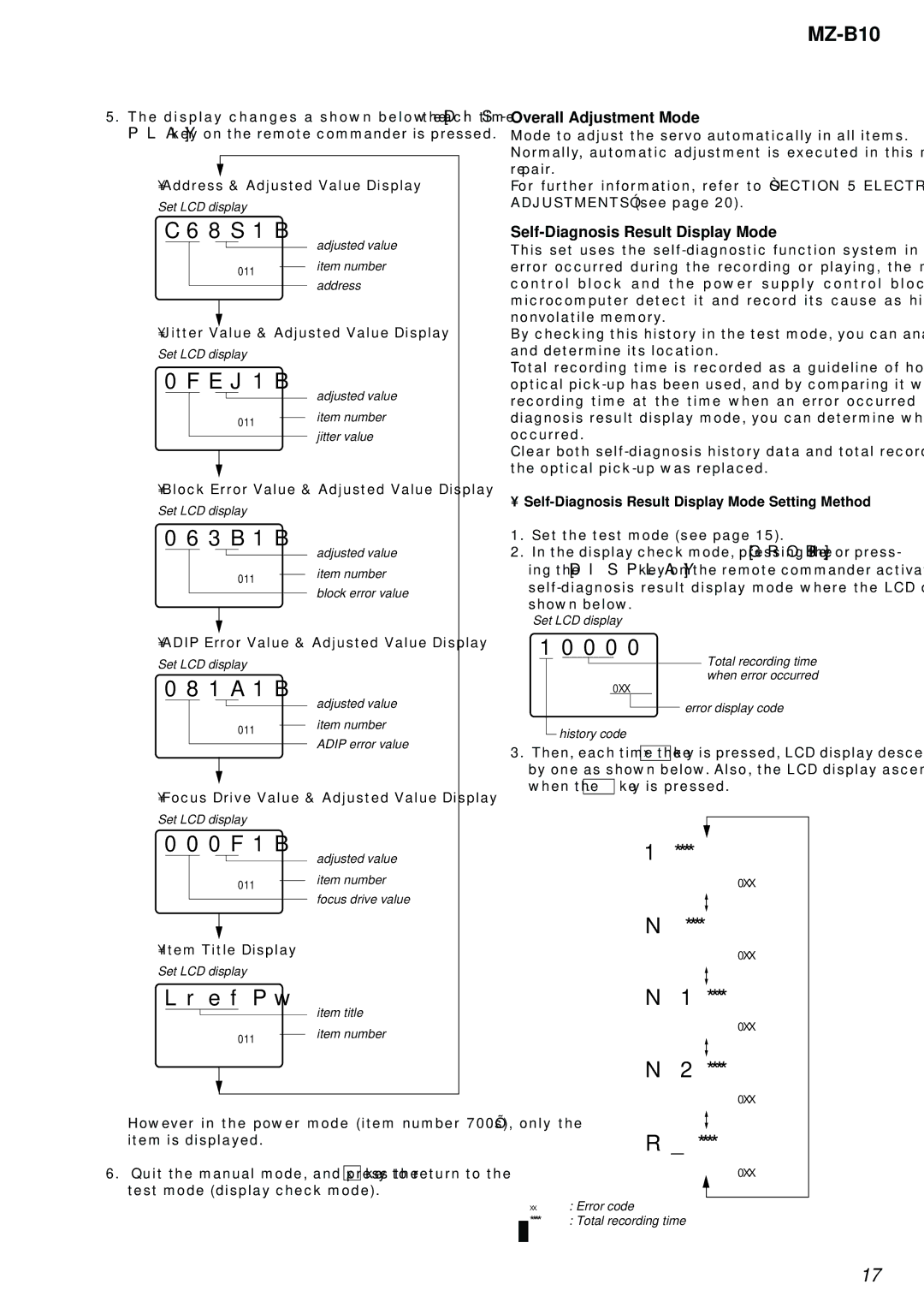
5.The display changes a shown below each time the [DIS- PLAY] key on the remote commander is pressed.
• Address & Adjusted Value Display
Set LCD display
C68S1B
|
|
|
|
|
|
|
| adjusted value |
|
|
| 011 |
|
| |||
|
|
|
|
| item number | |||
|
|
|
|
| ||||
|
|
|
|
|
|
|
| address |
|
|
|
|
|
|
|
| |
• Jitter Value & Adjusted Value Display
Set LCD display
0FEJ1B
|
|
|
|
|
|
|
| adjusted value |
|
|
| 011 |
|
| |||
|
|
|
|
| item number | |||
|
|
|
|
| ||||
|
|
|
|
|
|
|
| jitter value |
|
|
|
|
|
|
|
| |
• Block Error Value & Adjusted Value Display
Set LCD display
063B1B
|
|
|
|
|
|
|
| adjusted value |
|
|
| 011 |
|
| |||
|
|
|
|
| item number | |||
|
|
|
|
| ||||
|
|
|
|
|
|
|
| block error value |
|
|
|
|
|
|
|
| |
• ADIP Error Value & Adjusted Value Display
Set LCD display
081A1B
|
|
|
|
|
|
|
| adjusted value |
|
|
| 011 |
|
| |||
|
|
|
|
| item number | |||
|
|
|
|
| ||||
|
|
|
|
|
|
|
| ADIP error value |
|
|
|
|
|
|
|
| |
• Focus Drive Value & Adjusted Value Display
Set LCD display
000F1B
![]() adjusted value 011 item number
adjusted value 011 item number
focus drive value
• Item Title Display
Set LCD display
LrefPw
![]() item title 011 item number
item title 011 item number
However in the power mode (item number 700’s), only the item is displayed.
6.Quit the manual mode, and press the x key to return to the test mode (display check mode).
MZ-B10
Overall Adjustment Mode
Mode to adjust the servo automatically in all items.
Normally, automatic adjustment is executed in this mode at the repair.
For further information, refer to “SECTION 5 ELECTRICAL ADJUSTMENTS” (see page 20).
Self-Diagnosis Result Display Mode
This set uses the
By checking this history in the test mode, you can analyze a fault and determine its location.
Total recording time is recorded as a guideline of how long the optical
Clear both
• Self-Diagnosis Result Display Mode Setting Method
1.Set the test mode (see page 15).
2.In the display check mode, pressing the [GROUP]key or press- ing the [DISPLAY] key on the remote commander activates the
Set LCD display
1 | 0000 |
|
|
| Total recording time | ||||
|
|
|
|
|
|
|
|
| |
|
|
|
|
|
|
|
|
| |
|
|
|
|
| 0XX |
| when error occurred | ||
|
|
|
|
|
|
| |||
|
|
|
|
|
|
|
| error display code | |
|
|
| history code | ||||||
|
|
|
|
| |||||
|
|
|
|
| |||||
3. Then, each time the > key is pressed, LCD display descends by one as shown below. Also, the LCD display ascends by one when the . key is pressed.
1 ****
0XX
N****
0XX
N1****
0XX
N2****
0XX
R _ ****
0XX
XX: Error code
* * * * : Total recording time
17