MZ-B10
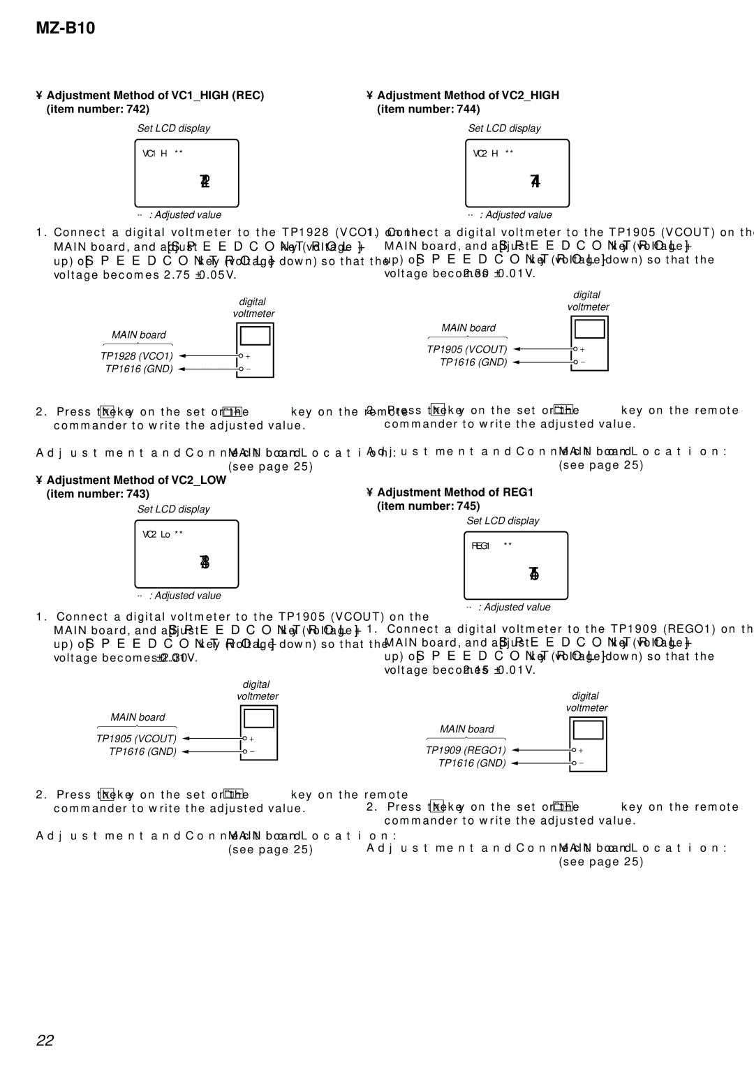
•Adjustment Method of VC1_HIGH (REC) (item number: 742)
Set LCD display
VC1 H **
742
**: Adjusted value
1.Connect a digital voltmeter to the TP1928 (VCO1) on the MAIN board, and adjust [SPEED CONTROL +] key (voltage up) or [SPEED CONTROL
digital voltmeter
MAIN board
TP1928 (VCO1)
TP1616 (GND) ![]()
•Adjustment Method of VC2_HIGH (item number: 744)
Set LCD display
VC2 Hi **
744
**: Adjusted value
1.Connect a digital voltmeter to the TP1905 (VCOUT) on the MAIN board, and adjust [SPEED CONTROL +] key (voltage up) or [SPEED CONTROL
digital voltmeter
MAIN board
TP1905 (VCOUT)
TP1616 (GND) ![]()
2.Press the X key on the set or the ![]()
![]()
![]() key on the remote commander to write the adjusted value.
key on the remote commander to write the adjusted value.
Adjustment and Connection Location: MAIN board (see page 25)
•Adjustment Method of VC2_LOW (item number: 743)
Set LCD display
VC2 Lo **
743
**: Adjusted value
1.Connect a digital voltmeter to the TP1905 (VCOUT) on the MAIN board, and adjust [SPEED CONTROL +] key (voltage up) or [SPEED CONTROL
digital voltmeter
MAIN board
TP1905 (VCOUT)
TP1616 (GND) ![]()
2.Press the X key on the set or the ![]() key on the remote commander to write the adjusted value.
key on the remote commander to write the adjusted value.
Adjustment and Connection Location: MAIN board (see page 25)
2.Press the X key on the set or the ![]()
![]()
![]() key on the remote commander to write the adjusted value.
key on the remote commander to write the adjusted value.
Adjustment and Connection Location: MAIN board (see page 25)
•Adjustment Method of REG1 (item number: 745)
Set LCD display
REG1 **
745
**: Adjusted value
1.Connect a digital voltmeter to the TP1909 (REGO1) on the MAIN board, and adjust [SPEED CONTROL +] key (voltage up) or [SPEED CONTROL
digital voltmeter
MAIN board
TP1909 (REGO1)
TP1616 (GND) ![]()
2.Press the X key on the set or the ![]()
![]()
![]() key on the remote commander to write the adjusted value.
key on the remote commander to write the adjusted value.
Adjustment and Connection Location: MAIN board (see page 25)
22
