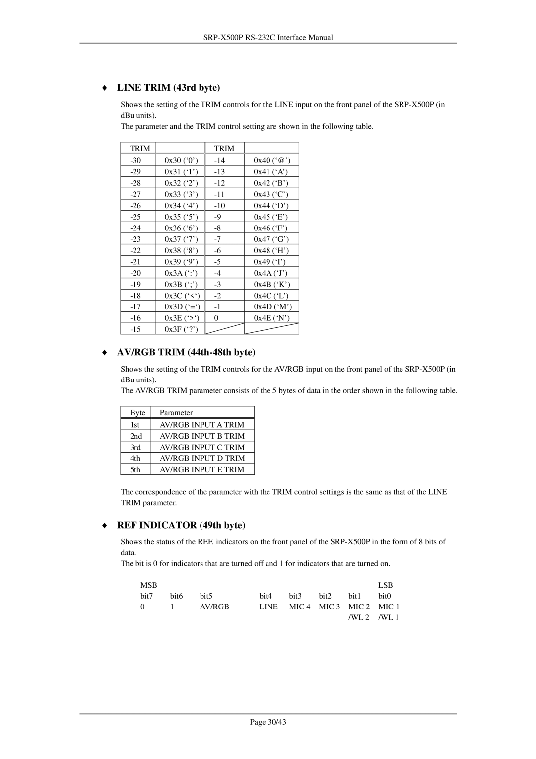
♦LINE TRIM (43rd byte)
Shows the setting of the TRIM controls for the LINE input on the front panel of the
The parameter and the TRIM control setting are shown in the following table.
TRIM
0x30 (‘0’) | |
0x31 (‘1’) | |
0x32 (‘2’) | |
0x33 (‘3’) | |
0x34 (‘4’) | |
0x35 (‘5’) | |
0x36 (‘6’) | |
0x37 (‘7’) | |
0x38 (‘8’) | |
0x39 (‘9’) | |
0x3A (‘:’) | |
0x3B (‘;’) | |
0x3C (‘<‘) | |
0x3D (‘=‘) | |
0x3E (‘>‘) | |
0x3F (‘?’) |
TRIM |
|
|
0x40 | (‘@’) | |
0x41 | (‘A’) | |
0x42 | (‘B’) | |
0x43 | (‘C’) | |
0x44 | (‘D’) | |
0x45 | (‘E’) | |
0x46 | (‘F’) | |
0x47 | (‘G’) | |
0x48 | (‘H’) | |
0x49 | (‘I’) | |
0x4A (‘J’) | ||
0x4B (‘K’) | ||
0x4C (‘L’) | ||
0x4D (‘M’) | ||
0 | 0x4E (‘N’) | |
♦AV/RGB TRIM (44th-48th byte)
Shows the setting of the TRIM controls for the AV/RGB input on the front panel of the
The AV/RGB TRIM parameter consists of the 5 bytes of data in the order shown in the following table.
Byte | Parameter |
1st | AV/RGB INPUT A TRIM |
2nd | AV/RGB INPUT B TRIM |
3rd | AV/RGB INPUT C TRIM |
4th | AV/RGB INPUT D TRIM |
5th | AV/RGB INPUT E TRIM |
The correspondence of the parameter with the TRIM control settings is the same as that of the LINE TRIM parameter.
♦REF INDICATOR (49th byte)
Shows the status of the REF. indicators on the front panel of the
The bit is 0 for indicators that are turned off and 1 for indicators that are turned on.
MSB |
|
|
|
|
|
| LSB |
bit7 | bit6 | bit5 | bit4 | bit3 | bit2 | bit1 | bit0 |
0 | 1 | AV/RGB | LINE | MIC 4 | MIC 3 | MIC 2 | MIC 1 |
|
|
|
|
|
| /WL 2 | /WL 1 |
Page 30/43