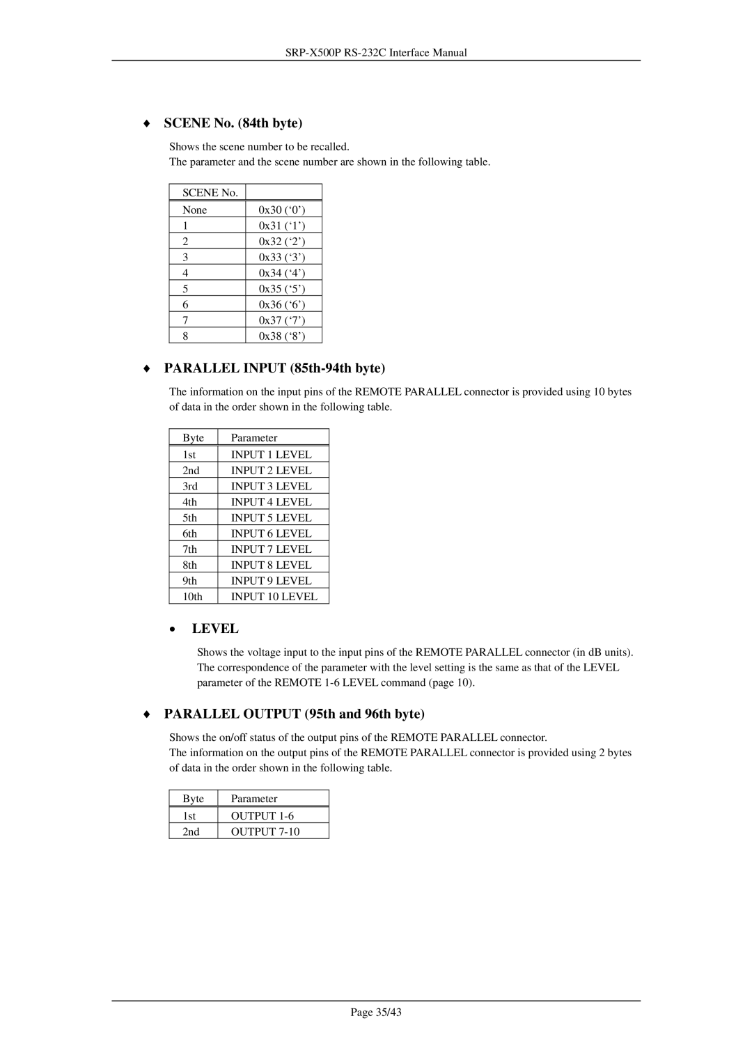
♦SCENE No. (84th byte)
Shows the scene number to be recalled.
The parameter and the scene number are shown in the following table.
SCENE No.
None | 0x30 (‘0’) |
1 | 0x31 (‘1’) |
2 | 0x32 (‘2’) |
3 | 0x33 (‘3’) |
4 | 0x34 (‘4’) |
5 | 0x35 (‘5’) |
6 | 0x36 (‘6’) |
7 | 0x37 (‘7’) |
8 | 0x38 (‘8’) |
♦PARALLEL INPUT (85th-94th byte)
The information on the input pins of the REMOTE PARALLEL connector is provided using 10 bytes of data in the order shown in the following table.
Byte | Parameter |
1st | INPUT 1 LEVEL |
2nd | INPUT 2 LEVEL |
3rd | INPUT 3 LEVEL |
4th | INPUT 4 LEVEL |
5th | INPUT 5 LEVEL |
6th | INPUT 6 LEVEL |
7th | INPUT 7 LEVEL |
8th | INPUT 8 LEVEL |
9th | INPUT 9 LEVEL |
10th | INPUT 10 LEVEL |
•LEVEL
Shows the voltage input to the input pins of the REMOTE PARALLEL connector (in dB units). The correspondence of the parameter with the level setting is the same as that of the LEVEL parameter of the REMOTE
♦PARALLEL OUTPUT (95th and 96th byte)
Shows the on/off status of the output pins of the REMOTE PARALLEL connector.
The information on the output pins of the REMOTE PARALLEL connector is provided using 2 bytes of data in the order shown in the following table.
Byte | Parameter |
1st | OUTPUT |
2nd | OUTPUT |
Page 35/43