For Machines Mfg. Since 8/11 | O P E R A T I O N |
Model SB1001 8K™ Lathe
Chuck & Faceplate Mounting
This lathe is equipped with a
Never use spindle speeds faster than the chuck RPM rating or the safe limits of your workpiece. Excessive spindle speeds greatly increase the risk of the workpiece or chuck being thrown from the machine with deadly force!
This lathe is shipped with the
A
If neither chuck can hold your workpiece, use a faceplate which has slots for
See Accessories on Page 46 for available
Chuck Installation
To ensure accurate work, it is extremely important to make sure the spindle nose and chuck mating surfaces/tapers are clean. Even a small amount of lint or debris can affect accuracy.
The chuck is properly installed when all camlocks are tight, the spindle and chuck tapers firmly lock together, and the back of chuck is firmly seated against the face of the spindle all the way
To install the chuck:
1.DISCONNECT LATHE FROM POWER!
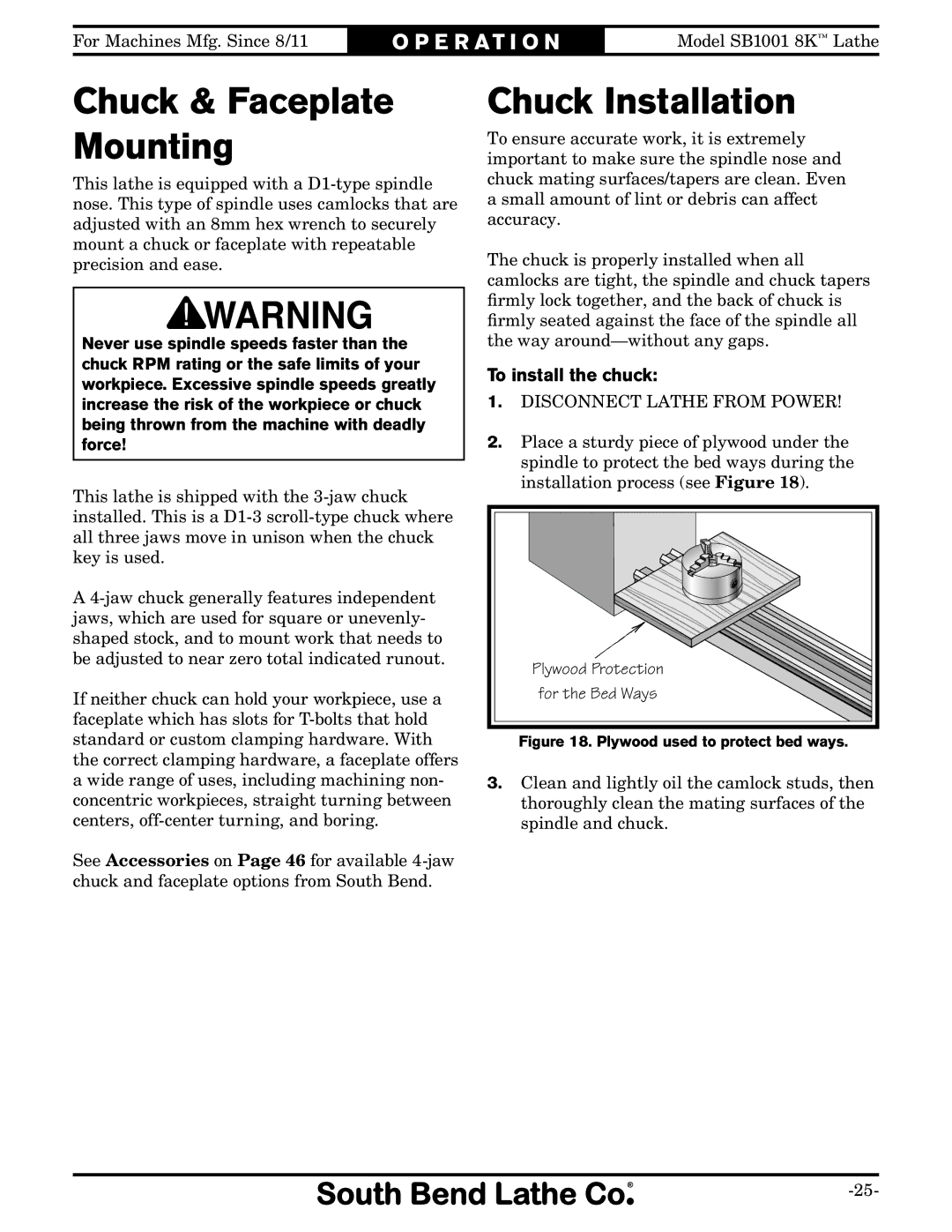
2.Place a sturdy piece of plywood under the spindle to protect the bed ways during the installation process (see Figure 18).
Plywood Protection |
for the Bed Ways |
Figure 18. Plywood used to protect bed ways.
3.Clean and lightly oil the camlock studs, then thoroughly clean the mating surfaces of the spindle and chuck.