Variable Speed Lathe
Scope of Manual
Updates
Customer Service
Manual Feedback
Table of Contents
Adjusting Drive Belts
About This Machine
Foreword
8K Lathe
Identification
Master Power Switch
Basic Controls Components
Control Panel
Carriage Tailstock
Carriage components
#$ %
704040%2 140 +70
Basic Machine Safety
Understanding Risks of Machinery
F E T Y
Additional Metal Lathe Safety
Additional Chuck Safety
Preparation Overview
Required for Setup
For Cleaning & Assembly
Typical preparation process is as follows
Full-Load Current Rating
Power Supply Requirements
Availability
Circuit Requirements
Grounding Requirements
Extension Cords
Unpacking
Inventory
Cleaning & Protecting
Before cleaning, gather the following
Basic steps for removing rust preventative
Location
Mounting
Leveling & Mounting
Leveling
Machine Base Work bench
Disconnecting Power
Power Connection
Connecting Power
Lubricating Lathe
Test Run
To test run your machine
Engaged
Spindle Break-In
Recommended Adjustments
Factory adjustments that should be verified
To perform the spindle break-in
Operation Overview
Chuck Installation
To install the chuck
Correct
Chuck Removal
Scroll Chuck Clamping
To remove the chuck
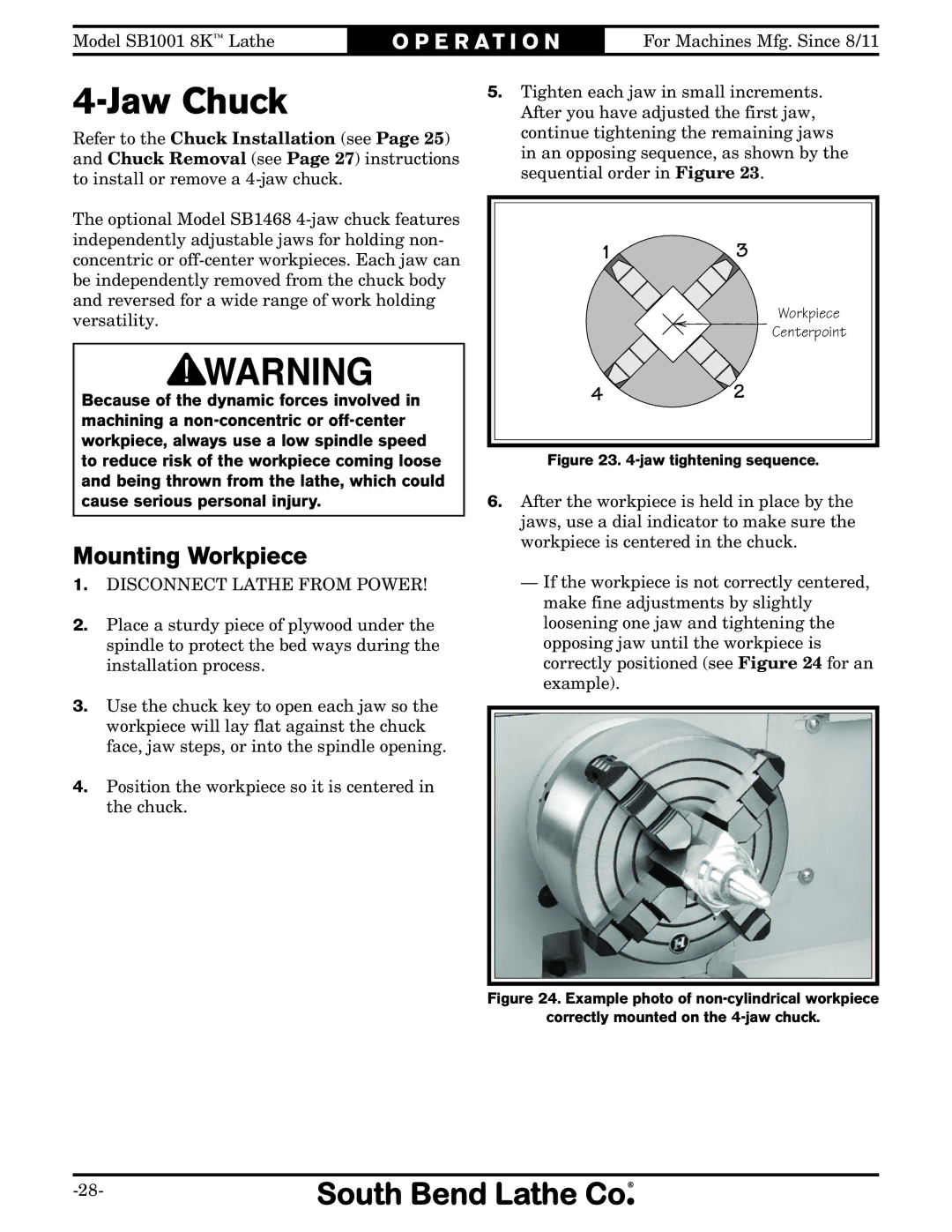
Jaw Chuck
Mounting Workpiece
Faceplate
To mount a non-concentric workpiece to the faceplate
To install tooling in the tailstock
Using Quill
Installing Tooling
Tailstock
To offset the tailstock
Offsetting Tailstock
Aligning Tailstock to Spindle Centerline
To align the tailstock to the spindle centerline
Looking down from above Move tailstock toward
Centers
Dead Centers
Live Centers
Removing Center from Spindle
Mounting Center in Spindle
Mounting Center in Tailstock
To mount a center in the tailstock
Carriage & Slide Locks
Mounting Workpiece Between Centers
Compound Rest
Installing Tool
To install a tool in the tool post
Four-Way Tool Post
Center
Aligning Cutting Tool with Spindle Centerline
To align the cutting tool with the tailstock
Top View
Manual Feed
Spindle Speed
Selecting Spindle Speed Range
To Change the Drive Belt Position
Tools Needed Qty
Timing Belts & Pulleys
Power Feed Threading Setup
Selecting Spindle Speed
Pulley Deflection
Setting Power Feed Rate
Setting Power Feed Rate of 0.0041/rev
Setting Threading Controls
Setting Thread Pitch of 12 TPI
16 B
Thread Dial
10, 14, or 18 TPI
Thread Dial Chart
12, 20, or 28 TPI
16, 24, or 32 TPI
Changing Feed Direction
To change the position of the feed direction gears
Accessories
SB1281-MT#2 High-Performance Live Center Set
SB1470-Steady Rest for SB1001 SB1471-Follow Rest for SB1001
SB1245-MT#2 Bull Nose Center
SB1391-D1-3 Back Plate
SB1354-South Bend Cast-Iron Workbench Legs, 1 Pair
Ongoing
Maintenance Schedule
Daily, After Operations
Daily, Before Operations
Lubrication
Spindle Bearings
Oil Gun
Feed Direction Gears
To lubricate the feed direction gears
Grease Fittings
Longitudinal Leadscrew
Jaw Chuck
Bedways & Slides
To prepare the lathe for storage
Leadscrew End Play Adjustment
Machine Storage
To remove leadscrew end play
Gib Adjustment
To adjust the saddle gib
Saddle Gib
Adjusting Drive Belts
To adjust the drive belts
Cross Slide & Compound Rest Gibs
Pulley Deflection
Trou B Leshooti NG
Trou B Leshooti NG
Electrical Safety Instructions
Wiring Diagram Color KEY
Electrical Cabinet Wiring Diagram
A12-30-10 To ON/OFF
Headstock
Description
Bed & Timing-Belt
Bed & Timing-Belt Pulleys Parts List
Saddle & Cross Slide
Compound Rest & Tool Post
Tool Post Lever
Apron
Quill
Electrical & End Cover
723 701 728
Labels
Door Closed Label
Page
Page
Warranty
#TS14279