Model SB1029 | E L E C T R I C A L | For Machines Mfg. Since 8/09 |
Rewiring for 440V | 6 | 7 | 0 | U | V | W | U1 | V1 | W1 | R | S | T | |
Wiring diagrams are provided in this section | 6 | 7 | 0 | U | V | W | U1 | V1 | W1 | R | S | T | |
showing the Model SB1029 wired for both 220V | |||||||||||||
|
|
|
|
|
|
|
|
|
|
| GND | ||
and 440V. Refer to these diagrams if needed |
|
|
|
|
|
|
|
|
|
|
| ||
when following this procedure. Additionally, |
|
| 0 | U | V | W |
|
|
| R | S | T | |
|
|
|
|
|
|
|
|
|
|
|
| ||
you must purchase 440V Conversion Kit (Part |
|
|
|
|
|
|
|
|
|
|
|
| |
No. PSB1029510) in order to complete the |
|
|
|
|
|
|
|
|
|
|
|
| |
conversion. |
|
|
|
|
|
|
|
|
|
|
|
|
Hardwiring to Power Source | Incoming |
Power Cord |
Hardwire setups require power supply lines to |
|
|
|
|
| ||||
be enclosed inside of conduit that is securely |
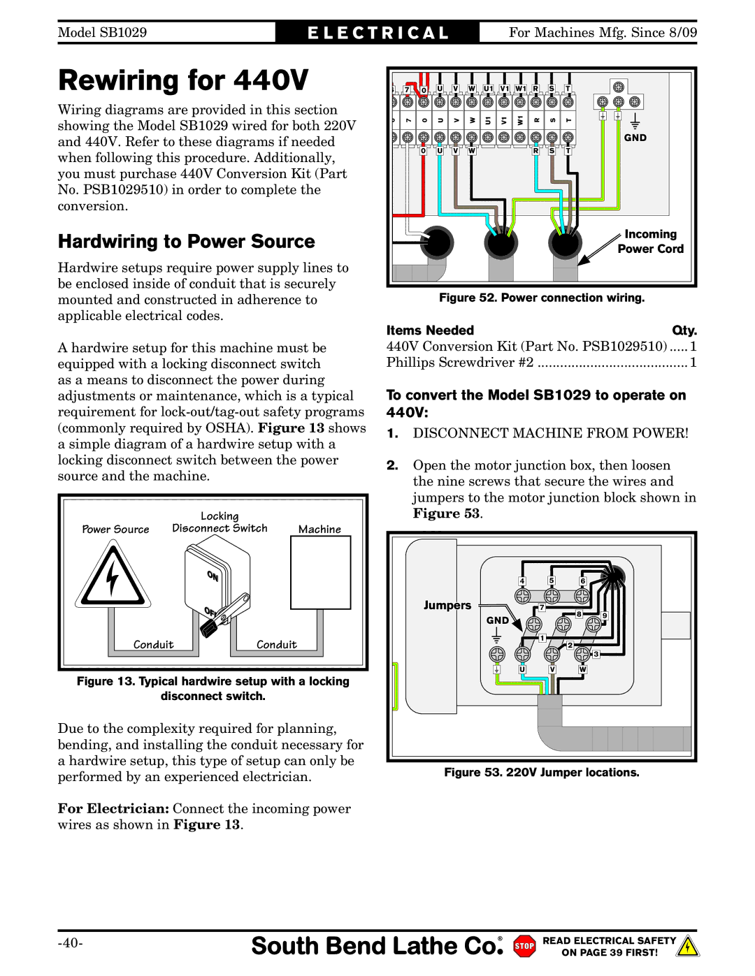
| Figure 52. Power connection wiring. | |||||||
mounted and constructed in adherence to |
| ||||||||
applicable electrical codes. |
|
| Items Needed |
|
| Qty. | |||
|
|
|
|
|
| ||||
A hardwire setup for this machine must be | 440V Conversion Kit (Part No. PSB1029510) ..... 1 | ||||||||
equipped with a locking disconnect switch | Phillips Screwdriver #2 ........................................ 1 | ||||||||
as a means to disconnect the power during | To convert the Model SB1029 to operate on | ||||||||
adjustments or maintenance, which is a typical | |||||||||
requirement for | 440V: |
|
|
| |||||
(commonly required by OSHA). Figure 13 shows | 1. DISCONNECT MACHINE FROM POWER! | ||||||||
a simple diagram of a hardwire setup with a | |||||||||
|
|
|
|
| |||||
locking disconnect switch between the power | 2. | Open the motor junction box, then loosen | |||||||
source and the machine. |
|
| |||||||
|
|
| the nine screws that secure the wires and | ||||||
|
|
|
|
| |||||
|
|
|
|
| jumpers to the motor junction block shown in | ||||
| Locking |
|
|
| Figure 53. |
|
|
| |
Power Source | Disconnect Switch | Machine |
| oto |
|
|
| ||
|
|
|
|
| 4 | 5 | 6 |
| |
|
|
|
|
| Jumpers | 7 | 8 | 9 | |
|
|
|
|
| GND |
| |||
|
|
|
|
|
|
|
| ||
Conduit | Conduit |
|
|
| 1 | 2 |
| ||
|
|
|
| 3 | |||||
|
|
|
|
|
|
|
| ||
Figure 13. Typical hardwire setup with a locking |
| U | V | W |
| ||||
|
|
|
|
| |||||
| disconnect switch. |
|
|
|
|
|
| ||
Due to the complexity required for planning, |
|
bending, and installing the conduit necessary for |
|
a hardwire setup, this type of setup can only be | Figure 53. 220V Jumper locations. |
performed by an experienced electrician. |
For Electrician: Connect the incoming power wires as shown in Figure 13.
READ ELECTRICAL SAFETY | |
| ON PAGE 39 FIRST! |
