For Machines Mfg. Since 8/09 |
| E L E C T R I C A L | Model SB1029 | |||||
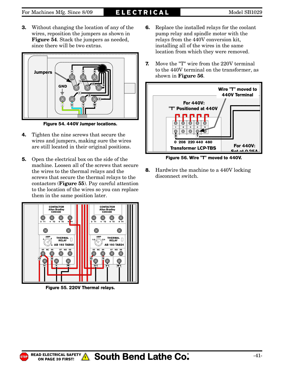
3. Without changing the location of any of the | 6. Replace the installed relays for the coolant | |||||||
wires, reposition the jumpers as shown in |
| pump relay and spindle motor with the | ||||||
Figure 54. Stack the jumpers as needed, |
| relays from the 440V conversion kit, | ||||||
since there will be two | extras. |
|
|
|
|
| installing all of the wires in the same | |
|
|
|
| |||||
Motor |
|
|
|
|
| location from which they were removed. | ||
|
|
|
| |||||
|
|
|
| 7. Move the "T" wire from the 220V terminal |
Jumpers | 4 | 5 | 6 | to the 440V terminal on the transformer, as |
|
|
| shown in Figure 56. | |
|
|
|
|
7 | 8 |
| |
GND | 9 | ||
| |||
1 |
| Wire "T" moved to | |
| 440V Terminal | ||
2 |
| ||
|
| 3 |
U | V | W |
| For 440V: |
| |||
|
|
| "T" Positioned at 440V |
| ||||
Figure 54. 440V Jumper locations. | 1 | 2 | 3 | 4 | 5 |
| ||
|
|
|
| |||||
4. Tighten the nine screws that secure the | R |
|
| T |
|
| ||
wires and jumpers, making sure the wires | 0 208 220 440 480 | For 440V: | ||||||
are still located in their original positions. | Transformer | |||||||
|
|
| 0 | 12 | 24 | 0 | 110 | Set at 0.25A |
|
|
|
| |||||
5. Open the electrical box on the side of the | Figure 56. Wire "T" moved to 440V. |
machine. Loosen all of the screws that secure | 8. Hardwire the machine to a 440V locking |
the wires to the thermal relays and the | |
screws that secure the thermal relays to the | disconnect switch. |
contactors (Figure 55). Pay careful attention |
|
to the location of the wires so you can replace |
|
them in the same position later. |
|
1 | L1 | 3 | L2 | 5 | L3 | 7 | L4 | 1 | L1 | 3 | L2 | 5 | L3 | 7 | L4 |
|
| CONTACTOR |
|
|
|
| CONTACTOR |
|
| ||||||
|
| Allen Bradley |
|
|
|
| Allen Bradley |
|
| ||||||
|
|
| C09400 |
|
|
|
|
|
| C09400 |
|
|
| ||
2 | T1 | 4 | T2 | 6 | T3 | 8 | T4 | 2 | T1 | 4 | T2 | 6 | T3 | 8 | T4 |
AMP
4![]() 5
5
THERMAL
RELAY
| AMP |
| THERMAL |
1.6 |
| 2.4 | |
| RELAY | ||
|
|
|
|
| 6 | AB 193 TAB60 |
|
| AB 193 TAB24 | ||||
95 | NC | 96 | 97 | NO | 98 | 95 | NC | 96 | 97 | NO 98 |
O |
| 8 |
|
|
| O |
| 9 |
|
|
U |
|
| V |
| W | U1 | V1 |
| W1 | |
Figure 55. 220V Thermal relays.
READ ELECTRICAL SAFETY | |
ON PAGE 39 FIRST! |
|