Manuals
/
Southbend
/
Power Tools
/
Lathe
Southbend
SB1052F TURN-X
owner manual
Electrical Box, Electrical box
Models:
SB1052F TURN-X
1
97
136
136
Download
136 pages
44.86 Kb
94
95
96
97
98
99
100
101
Specs
Install
Parts list
Thread Dial Chart
Dial Indicator
Wiring Overview
Warranty
Maintenance
Configuration Examples
Accessories
Page 97
Image 97
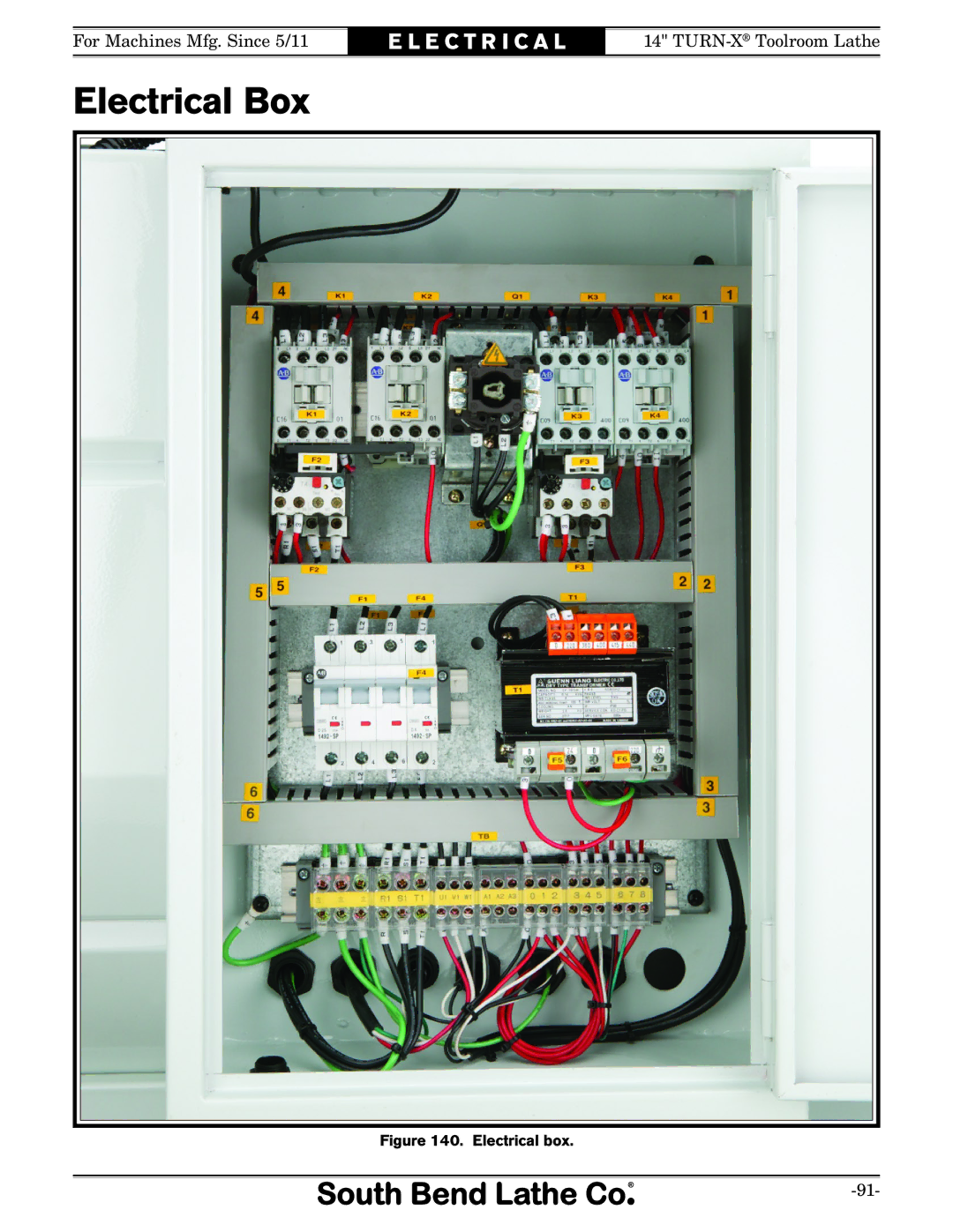
For Machines Mfg. Since 5/11
E L E C T R I C A L
14"
TURN-X
®
Toolroom Lathe
Electrical Box
Figure 140. Electrical box.
-91-
Page 96
Page 98
Page 97
Image 97
Page 96
Page 98
Contents
New & Changed Parts
Manual Insert
Model SB1052F
Main Specifications
Other
TURN-XTOOLROOM Lathe
Customer Service
Updates
Scope of Manual
Manual Feedback
Table of Contents
Accessories Maintenance
About This Machine
Features
Foreword
Capabilities
Identification
General Identification
Two-Speed Motor Switch
Master Power Switch
Controls Components
Carriage
Control Panel
Tailstock
Safety Foot Brake
End Gears
Product Specifications
Main Motor
Tailstock Information
Construction
Understanding Risks of Machinery
Basic Machine Safety
F E T Y
Additional Metal Lathe Safety
Additional Chuck Safety
Things Youll Need
Preparation Overview
Typical preparation process is as follows
Availability
Power Supply Requirements
Full-Load Current Rating
Circuit Requirements
Extension Cords
Grounding Requirements
Unpacking
Pre-Installed Not Shown Qty
Inventory
Main Inventory 1 Figure Qty
Before cleaning, gather the following
Cleaning & Protecting
Basic steps for removing rust preventative
Location
Lifting & Moving
Loooking at Lifting Setup from Tailstock End
To lift and move the lathe
Leveling
Leveling & Mounting
Lubricating Lathe
Assembly
Bolting to Concrete Floors
To connect the power cord to the lathe
Power Connection
Adding Coolant
To Plug
To test run your machine
Test Run
Spindle Speed
Neutral
Lever Set To
50 RPM
Feed Control Lever Disengaged Halfnut
Disengaged
E P a R a T I O N
Factory adjustments that should be verified
Recommended Adjustments
Spindle Break-In
To perform the spindle break-in
Operation Overview
Chuck & Faceplate Mounting
Installation & Removal Devices
To install the chuck
Chuck Installation
Registration Marks
Chuck Removal
To remove the chuck
Jaw Chuck
Scroll Chuck Clamping
Mounting Workpiece
Jaw tightening sequence
Faceplate
Tailstock
Using Quill
Positioning Tailstock
To mount a non-concentric workpiece to the faceplate
To install tooling in the tailstock
Installing Tooling
Removing Tooling
Offsetting Tailstock
To offset the tailstock
Tools Needed Qty
Items Needed Qty
Aligning Tailstock to Spindle Centerline
To align the tailstock to the spindle centerline
Dead Centers
Centers
Mounting Dead Center in Spindle
Live Centers
Removing Center from Spindle
Mounting Center in Tailstock
Mounting Workpiece Between Centers
Removing Center from Tailstock
Steady Rest
To install and use the steady rest
Carriage & Slide Locks
Follow Rest
Compound Rest
To install a tool in the tool post
Four-Way Tool Post
Tool Needed Qty
To align the cutting tool with the tailstock center
Aligning Cutting Tool with Spindle Centerline
Top View
Side View
Micrometer Stop
Adjustable Feed Stop
To set the micrometer stop
Spindle Speed
Manual Feed
Configuration Examples
Setting Spindle Speed
Setting Spindle Speed of 215 RPM
RPM or lower when using the high H gearbox range
Setting Spindle Speed of 1600 RPM
Power Feed
Quick-change Gearbox Feed Levers
Power Feed Controls
Setting Power Feed Rate of 0.18mm/rev
Setting Power Feed Rate
End Gears
Standard End Gear Configuration
24T 56T 44T
57T
Configuring End Gears
Alternate Configuration
To configure the end gears
Tools Needed Qty
Threading
Setting Metric Thread Pitch
Headstock Threading Controls
Apron Threading Controls
When required and prevent an apron crash
Thread Dial
Feed Control Lever
TPI Divisible By
Thread Dial Chart
Even TPI Not Divisible By
Odd Numbered TPI
⁄4 or 3⁄4 Fractional TPI
Chip Drawer
27⁄8 TPI
To use the coolant system on your lathe
Coolant System
SB1279-10 Pc. Precision 5-C Collet Set
Accessories
D1-5 Back Plates SB1397-6⁜1⁄4 SB1399-8⁜1⁄4 SB1401-10⁜1⁄2
SB1264-Collect Attachment
SB1354-South Bend Cast-Iron Workbench Legs, 1 Pair
Keyless Integral Chucks SB1379-MT #3 1⁄2 SB1380-MT #3 5⁄8
SB1251-Machinists Oak Tool Box
SB1365-Way Oil
Maintenance Schedule
South Bend Lathe Co. Lathe Monthly Maintenance Chart
Headstock
Lubrication
Apron
Quick-Change Gearbox
Draining Oil
Draining Oil & Flushing Reservoir
Longitudinal Leadscrew
One-Shot Oiler
Tailstock ball oilers
Ball Oilers & Oil Cup
Lubricating
Handling & Care
Hazards
Coolant System Service
Changing Coolant
Adding Fluid
Items Needed Qty
To change the coolant
To prepare the lathe for storage
Machine Storage
Compound Rest
Backlash Adjustment
Cross Slide
Gib Adjustment
Leadscrew End Play Adjustment
To remove leadscrew end play
Front saddle gib adjustment screw Carriage Lock Clamp
To adjust the V-belts
Half Nut Adjustment
To adjust the half nut
Belts
To adjust the brake and brake switch
Brake & Switch
Remove the pedal stop shown in Figure
To replace the shear pin
Leadscrew Shear Pin Replacement
Shear pin bores aligned
Gap Removal
Gap Insert Removal & Installation
Gap Installation
Symptom Possible Cause Possible Solution
Symptom Possible Cause Possible Solution
Symptom Possible Cause Possible Solution
Wiring Diagram Color KEY
Electrical Safety Instructions
Wiring Overview
Correcting Phase Polarity Wiring
To correct wiring that is out of phase
Component location index
Component Location Index
WorkToLamp, Switch,SafetyPage
Electrical Cabinet Wiring
Electrical box
Electrical Box
Spindle Motor
Cutting Fluid Pump Wiring
Speed Motor Switch
Spindle Switches
Control Panel Wiring
End Gear Cover Safety switch location Chuck Guard Switch
Additional Component Wiring
Headstock Cover
R T S
Headstock Controls Parts List
Headstock Internal Gears
Headstock Internal Gears Parts List
Headstock Transfer Gears
207
Outboard Splined Shaft G1
Gearbox Gears Parts List
Gearbox Controls
Fork Support Partition
Gearbox Controls Parts List
Apron Front View
Apron Front View Parts List
Apron Rear View
Apron Rear View Parts List
Compound Rest & Tool Post
Saddle Top View
PRP28M Roll PIN 5 X
Saddle Top View Parts List
Saddle Bottom View
Bed Stop
Dial Indicator
TURN-X
Shafts
Bed & Shafts Parts List
905 904 903 914 902 913 901
Main Motor
Description
Main Motor Parts List
Stands & Panels
Cabinets & Panels Parts List
1201 1203 1204 1205 1240 1206 1207 1214
Tailstock Parts List
1300 1303 1304 1305 1306 1309 1307 1310 1311 1308 1312A 1315
Electrical Cabinet & Control Panel
Master Power Switch
1502V2 1519 1511 1512 1513 1516 1514 1515
Front Machine Labels
Rear & Side Machine Labels
220V 3-PHASE Label
Warranty
#TS14364
Top
Page
Image
Contents