EVS Toolroom Lathe w/DRO
Manual Feedback
Updates
Customer Service
Scope of Manual
Table of Contents
Warranty
Capabilities
Features
About This Machine
Foreword
General identification Model SB1060PF shown
General Identification
Headstock Controls
Master Power Switch
Controls Components
Carriage Controls
Control Panel
Tailstock Controls
Adjustable carriage clutch knob
Foot brake and spindle ON/OFF lever
Foot Brake
Model SB1059F, SB1060PF, SB1061PF EVS Toolroom Lathe w/DRO
Product Specifications
Main Motor
Tailstock Information
Construction
Model Number SB1042PF SB1043PF SB1045PF
Model SB1042PF, SB1043PF, SB1045PF EVS Toolroom Lathe w/DRO
Main Motor
Headstock Information
Construction
Understanding Risks of Machinery
Basic Machine Safety
F E T Y
Additional Metal Lathe Safety
Additional Chuck Safety
Typical preparation process is as follows
Preparation Overview
Things Youll Need
Circuit Requirements
Power Supply Requirements
Availability
Full-Load Current Rating
440V Operation
Grounding Requirements
Main Inventory 1 Figure Qty
Installed & Not Shown Qty
Unpacking
Inventory
Basic steps for removing rust preventative
Cleaning & Protecting
Before cleaning, gather the following
Location
To lift and move the lathe
Lifting & Moving
Leveling
Leveling & Mounting
Bolting to Concrete Floors
Assembly
Lubricating Lathe
Adding Coolant
Power Connection
Supply
Connecting Power
To test run your machine
Test Run
Engaged
E P a R a T I O N
To perform the spindle break-in
Recommended Adjustments
Factory adjustments that should be verified
Spindle Break-In
Operation Overview
Chuck & Faceplate Mounting
Installation & Removal Devices
To install the chuck
Chuck Installation
To remove the chuck
Chuck Removal
Registration Marks
Mounting Workpiece
Scroll Chuck Clamping
Jaw Chuck
Jaw tightening sequence
Faceplate
To mount a non-concentric workpiece to the faceplate
Using Quill
Tailstock
Positioning Tailstock
To install tooling in the tailstock
Installing Tooling
Tools Needed Qty
Offsetting Tailstock
Removing Tooling
To offset the tailstock
To align the tailstock to the spindle centerline
Aligning Tailstock to Spindle Centerline
Items Needed Qty
Dead Centers
Centers
Mounting Center in Tailstock
Live Centers
Mounting Dead Center in Spindle
Removing Center from Spindle
Mounting Workpiece Between Centers
Removing Center from Tailstock
Steady Rest
To install and use the steady rest
To set the compound rest at a certain angle
Follow Rest
Compound Rest
Tool Needed Qty
Aligning Cutting Tool with Spindle Centerline
Installing Tool
To install a tool in the tool post
Four-Way Tool Post
Side View
Micrometer Stop
To align the cutting tool with the tailstock center
Top View To set the micrometer stop
Spindle Speed
Manual Feed
Setting Spindle Speed
Power Feed
Gearbox range lever
Power Feed Controls
Apron feed selection and direction knobs
Example Power Feed Rate of 0.0025/rev
Setting Power Feed Rate
Configuring End Gears
End Gears
Standard End Gear Configuration
Alternate End Gear Configuration
Example Metric Thread Pitch of 2.5mm
Threading Controls
Headstock & Gearbox Threading Controls
Engaged
Apron Controls
TPI Divisible By
Thread Dial Chart
Thread Dial
⁄4 or 3⁄4 Fractional TPI
Even TPI Not Divisible By
Odd Numbered TPI
⁄2 Fractional TPI
Coolant System
Chip Drawer
To use the coolant system on your lathe
Rod Support
SB1271-Taper Attachment
Accessories
SB1279-10 Pc. Precision 5-C Collet Set
SB1272-Collect Attachment
Maintenance Schedule
South Bend Lathe Co. Lathe Monthly Maintenance Chart
Headstock
Oil Pressure Safety Switch
Lubrication
Items Needed Qty
Checking & Adding Oil
Changing Headstock Oil
Draining headstock oil
To to change the headstock oil
Checking Oil Level
Quick-Change Gearbox
Apron
Draining Oil
Draining Oil & Flushing Reservoir
One-Shot Oiler
Ball Oilers
Longitudinal Leadscrew
Lubricating
End Gears
Handling & Care
Hazards
Coolant System Service
To change the coolant
Adding Fluid
Changing Coolant
To prepare the lathe for storage
Machine Storage
Cross Slide
Backlash Adjustment
Compound Rest
To remove leadscrew end play
Leadscrew End Play Adjustment
Gib Adjustment
Front saddle gib adjustment screw Carriage Lock Clamp
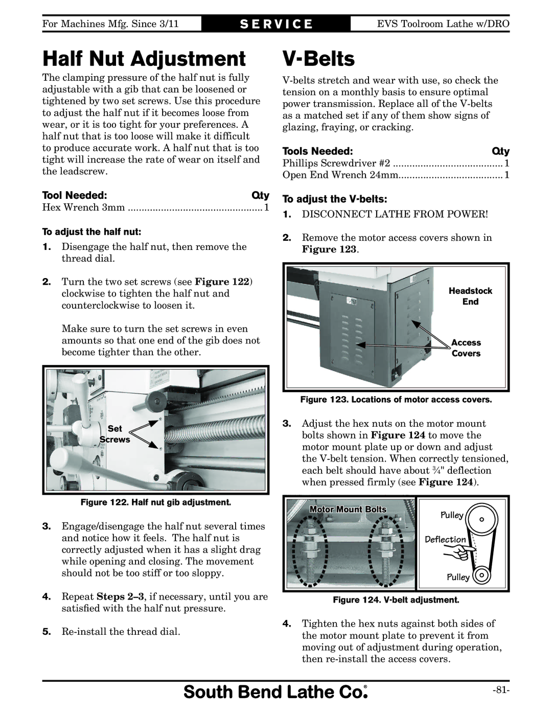
Belts
Half Nut Adjustment
To adjust the V-belts
To adjust the half nut
To replace the brake shoes
Brake Service
Needed Qty
Brake switch
To replace the shear pin
Leadscrew Shear Pin Replacement
Shear pin access
Gap Removal
Gap Insert Removal & Installation
Gap Installation
TR O U B L E S H O OTI N G
TR O U B L E S H O OTI N G
TR O U B L E S H O OTI N G
Wiring Diagram Color KEY
Electrical Safety Instructions
To correct wiring that is out of phase
Correcting Phase Polarity
ON/OFF
Wiring Overview
Component location index
Component Location Index
Page100
Electrical Box Wiring
To Incoming Power
Electrical box
Electrical Box
Motor
Spindle Motor
Oil Pump Motor & Pressure Sensor
Spindle ON/OFF Switch
Coolant Pump Wiring
Disconnect
Control Panel Wiring
Pontnet
Additional Component Wiring
Headstock Housing
Description
Headstock Housing Parts List
122
Headstock Gears
105
Pipe Plug 1/2 NPT
Headstock Gears Parts List
Gearbox
Gearbox
Description
Gearbox Parts List
110
Apron
112
Apron Parts List
114
720 723 724 719 726 716
Tool Post & Compound Rest
825
Saddle & Cross Slide
117
118
Saddle & Cross Slide Parts List
Bed & Shafts
BED GAP Piece SB1059F
Bed & Shafts Parts List
1016 1002 1001 1007 1006
End Gears SB1042PF, SB1043PF, SB1045PF
End Gears SB1059F, SB1060PF, SB1061PF
Motor & Headstock Oil System
PVA75
Motor & Headstock Oil System Parts List
Stand & Panels SB1042PF-43PF, SB1059F-61PF
PW03M Flat Washer 6MM
Stand & Panels Parts List SB1042PF-43PF, SB1059F-61PF
Stand & Panels SB1045PF
Upper Catch Tray
Stand & Panels Parts List SB1045PF
1312
Steady Rest Follow Rest
1558 1550 1551 1552 1554 1553 1555 1556 1559 1560
Micrometer Stop Thread Dial
Brake
Control Panel Viewed from Behind
Electrical Cabinet & Control Panel
1802
1910
Front Machine Labels
Rear Machine Labels
Warranty
Southbendlathe.com