Chassis Assembly
Chassis Assembly
Preparation
Identify the parts used in the chassis. Refer to the Kit Contents section for a list of parts in each bag.
•
•
•Hardware Bag: everything except the four 1” standoffs and eight of the
•Loose items: everything except the
Remove the paper from the (twelve) chassis pieces. (The Level 1 kit contains the chassis parts needed for all levels; keep the extra pieces somewhere convenient for use later.)
Cut the 1/2” x 2” strip of
Cut each 1/2” piece of shrink tubing in half. Slide one 1/4” piece onto the orange wire of a servo cable (you can gently pull to separate the colored wires, but don’t shorten the cable). Referring to the picture on the right, solder the orange wire to the “left” connection on the motor, keeping the shrink tubing away from the joint while you work. Slide the tubing over the connection and shrink it with a heat gun or hair dryer. Repeat with the red wire, and then for the second motor.
Trim the wires connected to the light sensors, leaving 6” of colored wire. Strip the insulation off
1/4” of the end of each wire, then tin those ends. Note: if you are using the optional ARC Board Connection Kit, connect male crimp pins to the light sensor wires and insert them into a
Using leftover wires from the light sensors, cut two 7” lengths of blue and two of white. Strip and tin ~1/4” on one end and 3/8” on the other end. (Do not use ARC Board Connection Kit parts here.)
Motors
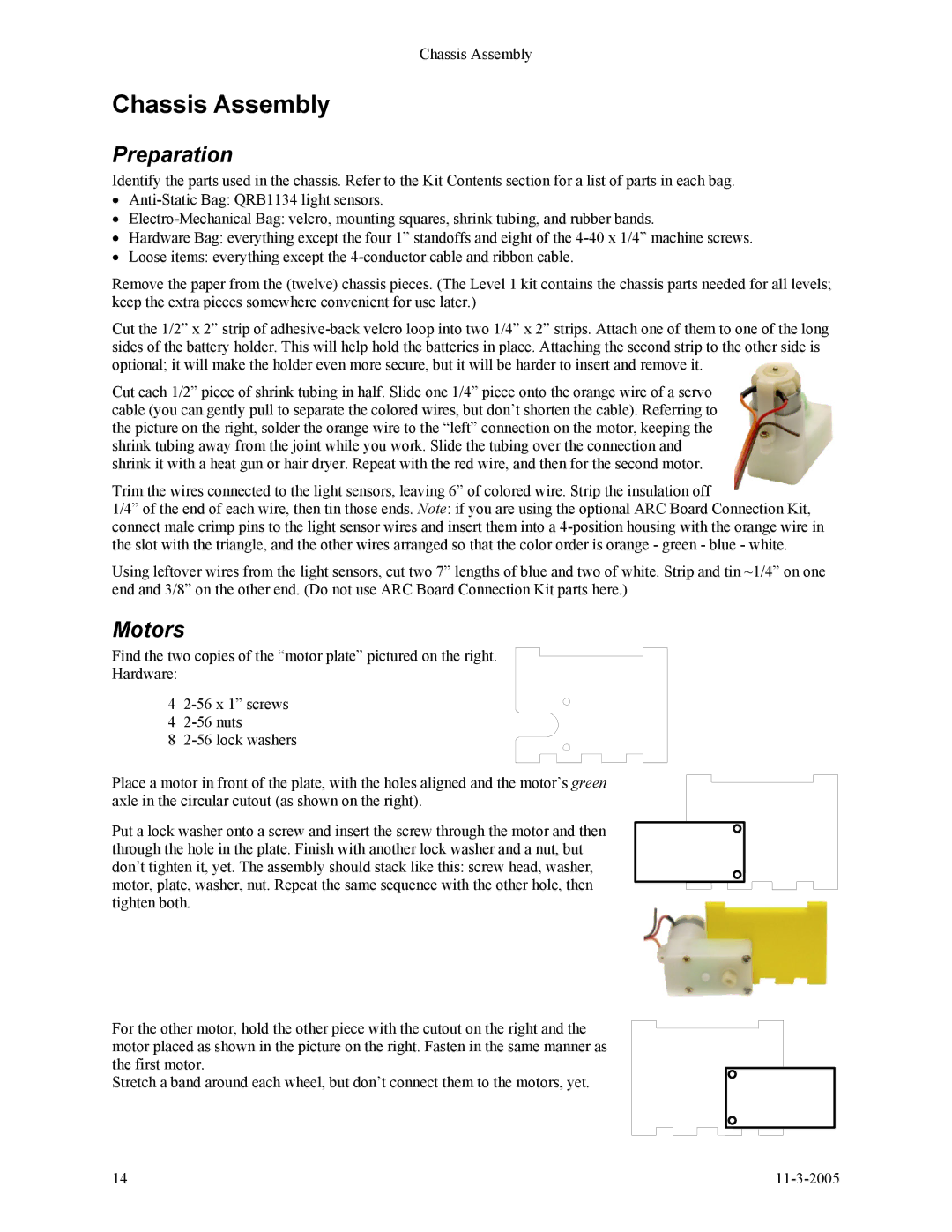
Find the two copies of the “motor plate” pictured on the right.
Hardware:
4
4
8
Place a motor in front of the plate, with the holes aligned and the motor’s green axle in the circular cutout (as shown on the right).
Put a lock washer onto a screw and insert the screw through the motor and then through the hole in the plate. Finish with another lock washer and a nut, but don’t tighten it, yet. The assembly should stack like this: screw head, washer, motor, plate, washer, nut. Repeat the same sequence with the other hole, then tighten both.
For the other motor, hold the other piece with the cutout on the right and the motor placed as shown in the picture on the right. Fasten in the same manner as the first motor.
Stretch a band around each wheel, but don’t connect them to the motors, yet.
14 |
