AVR Robot Controller 1.1 Hardware Description
Expansion Headers JP3 and JP10
Refer to the schematic for the connections to these headers. All CPU I/O, +5v, ground, +/- 10v and battery voltages are supplied. JP3 supplies +5v and ground from the analog section. JP10 supplies +5v, ground, +10v and –10v from the digital section. The +/-10v is from the serial interface chip and can only supply about 10ma of current. This is sufficient for one or two low powered op-amps. JP3 and JP10 are oriented with pin 1 toward the notch side of the CPU.
Left and Right Analog Inputs
These are the headers labeled “LEFT” and “RIGHT” at the front of the board, with the 3-connector sockets. They are raw analog inputs with filtered +5v and ground. They are intended to connect directly to the Sharp GP2D12 or 15 sensors. However any 0-5v output sensor may be used. You can also connect a potentiometer to these inputs for position feedback or variable input.
Left, Center, and Right Floor Sensor Inputs
These are the headers labeled “LF,” “CF,” and “RF” at the front of the board, with the 4-connector sockets. These match the pin-out of QRB1134 phototransistors. The resistors supplied with the kit are selected to work well with these sensors. Pin 1 is attached to the outer E (emitter) wire. Pin 4 is attached to the outer S (sensor) wire. If you do not want to commit the board to these sensors, you can replace the 180-ohm resistor with a piece of wire and leave out the 4.7k resistors. The resulting circuit is similar to the Left and Right analog inputs and allows +5v-powered sensors to be connected to the board.
Normal Wiring | Alternate Wiring |
Left and Right Motor Connectors
These are the headers labeled “LEFT” and “RIGHT” at the back of the board, with the 2x3 pin headers. The left and right motor connectors provide output from the H-bridge, power, ground, and two CPU I/O lines. The additional lines can be used to implement an encoder feedback or input mechanism, or can be used as output lines to drive a standard R/C servo.
H-bridge output
The H-bridge output is on the inner pins of the header and is directly connected to the 754410 H-bridge. This can supply up to 1A with a battery voltage of up to 24V. If you gut a servo and re-attach the servo cable wires to the motor, be aware that the two H-bridge output pins are not aligned with the power pins: you either need to wire the servo motor to Red, White, or connect the plug in reverse.
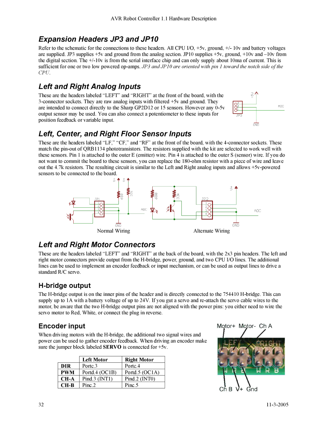
Encoder input
When driving motors with the H-bridge, the additional two signal wires and power can be used to gather encoder feedback. When driving an encoder make sure the jumper block labeled SERVO is connected for +5v.
| Left Motor | Right Motor |
DIR | Portc.3 | Portc.4 |
PWM | Portd.4 (OC1B) | Portd.5 (OC1A) |
CH-A | Pind.3 (INT1) | Pind.2 (INT0) |
CH-B | Pinc.2 | Pinc.5 |