AVR Robot Controller 1.1 Hardware Description
AVR Robot Controller 1.1 Hardware Description
The Level 1 Robot Kit ships with an ATmega16 microcontroller. The Atmel AVR microcontrollers are designed to be pin- and
Power
Power can be any source from
I/O Pins
The ATmega16 microcontroller has four
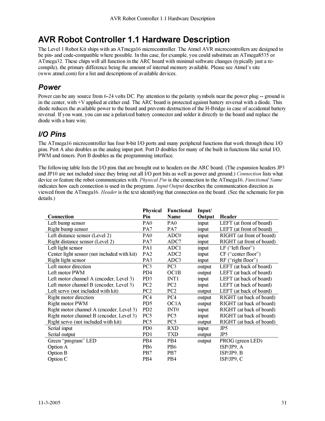
The following table lists the I/O pins that are brought out to headers on the ARC board. (The expansion headers JP3 and JP10 are not included since they bring out all I/O port bits as well as power and ground.) Connection lists what device or feature the robot communicates with. Physical Pin is the connection to the ATmega16. Functional Name indicates how each connection is used in the programs. Input/Output describes the communication direction as viewed from the ATmega16. Header is the text identifying that connection on the board. (See the schematic for pin details.)
| Physical | Functional | Input/ |
|
Connection | Pin | Name | Output | Header |
Left bump sensor | PA0 | PA0 | input | LEFT (at front of board) |
Right bump sensor | PA7 | PA7 | input | LEFT (at front of board) |
Left distance sensor (Level 2) | PA0 | ADC0 | input | RIGHT (at front of board) |
Right distance sensor (Level 2) | PA7 | ADC7 | input | RIGHT (at front of board) |
Left light sensor | PA1 | ADC1 | input | LF (“left floor”) |
Center light sensor (not included with kit) | PA2 | ADC2 | input | CF (“center floor”) |
Right light sensor | PA3 | ADC3 | input | RF (“right floor”) |
Left motor direction | PC3 | PC3 | output | LEFT (at back of board) |
Left motor PWM | PD4 | OC1B | output | LEFT (at back of board) |
Left motor channel A (encoder, Level 3) | PD3 | INT1 | input | LEFT (at back of board) |
Left motor channel B (encoder, Level 3) | PC2 | PC2 | input | LEFT (at back of board) |
Left servo (not included with kit) | PC2 | PC2 | output | LEFT (at back of board) |
Right motor direction | PC4 | PC4 | output | RIGHT (at back of board) |
Right motor PWM | PD5 | OC1A | output | RIGHT (at back of board) |
Right motor channel A (encoder, Level 3) | PD2 | INT0 | input | RIGHT (at back of board) |
Right motor channel B (encoder, Level 3) | PC5 | PC5 | input | RIGHT (at back of board) |
Right servo (not included with kit) | PC5 | PC5 | output | RIGHT (at back of board) |
Serial input | PD0 | RXD | input | JP5 |
Serial output | PD1 | TXD | output | JP5 |
Green “program” LED | PB4 | PB4 | output | PROG (green LED) |
Option A | PB6 | PB6 |
| ISP/JP9, A |
Option B | PB7 | PB7 |
| ISP/JP9, B |
Option C | PB4 | PB4 |
| ISP/JP9, C |
31 |
