Chassis Assembly
Flip the top plate over. The screws will be visible, and the standoffs will be underneath (and you should have a hole in the lower right corner).
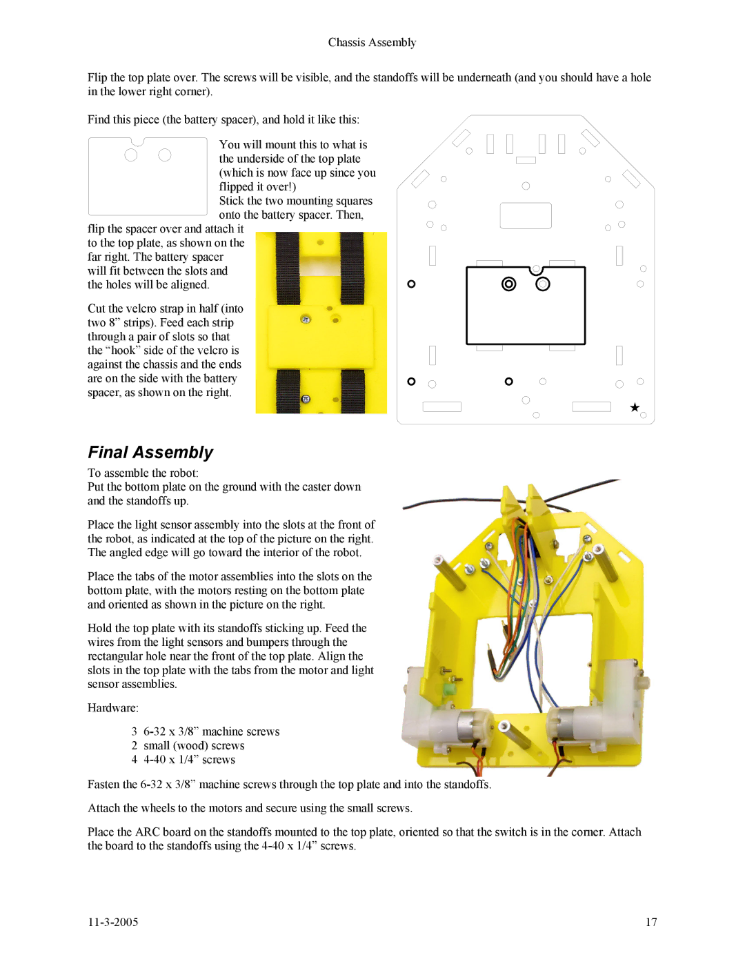
Find this piece (the battery spacer), and hold it like this:
You will mount this to what is the underside of the top plate (which is now face up since you flipped it over!)
Stick the two mounting squares onto the battery spacer. Then,
flip the spacer over and attach it to the top plate, as shown on the far right. The battery spacer will fit between the slots and the holes will be aligned.
Cut the velcro strap in half (into two 8” strips). Feed each strip through a pair of slots so that the “hook” side of the velcro is against the chassis and the ends are on the side with the battery spacer, as shown on the right.
Final Assembly
To assemble the robot:
Put the bottom plate on the ground with the caster down and the standoffs up.
Place the light sensor assembly into the slots at the front of the robot, as indicated at the top of the picture on the right. The angled edge will go toward the interior of the robot.
Place the tabs of the motor assemblies into the slots on the bottom plate, with the motors resting on the bottom plate and oriented as shown in the picture on the right.
Hold the top plate with its standoffs sticking up. Feed the wires from the light sensors and bumpers through the rectangular hole near the front of the top plate. Align the slots in the top plate with the tabs from the motor and light sensor assemblies.
Hardware:
3
2small (wood) screws
4
Fasten the
Attach the wheels to the motors and secure using the small screws.
Place the ARC board on the standoffs mounted to the top plate, oriented so that the switch is in the corner. Attach the board to the standoffs using the
17 |