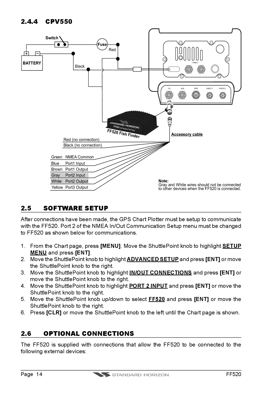
2.4.4CPV550
Switch
Fuse
Red
+ | - |
BATTERY
Black
Red (no connection)
Black (no connection)
Green | NMEA Common |
Blue | Port1 Input |
Brown | Port1 Output |
Gray | Port2 Input |
White | Port2 Output |
Yellow | Port3 Output |
1 RAM 2
I/O | AUX | GPS | VIDEO 1 | VIDEO 2 |
Accessory cable
Note:
Gray and White wires should not be connected to other devices when the FF520 is connected.
2.5SOFTWARE SETUP
After connections have been made, the GPS Chart Plotter must be setup to communicate with the FF520. Port 2 of the NMEA In/Out Communication Setup menu must be changed to FF520 as shown below for communications.
1.From the Chart page, press [MENU]. Move the ShuttlePoint knob to highlight SETUP MENU and press [ENT].
2.Move the ShuttlePoint knob to highlight ADVANCED SETUP and press [ENT] or move the ShuttlePoint knob to the right.
3.Move the ShuttlePoint knob to highlight IN/OUT CONNECTIONS and press [ENT] or move the ShuttlePoint knob to the right.
4.Move the ShuttlePoint knob to highlight PORT 2 INPUT and press [ENT] or move the ShuttlePoint knob to the right.
5.Move the ShuttlePoint knob up/down to select FF520 and press [ENT] or move the ShuttlePoint knob to the right.
6.Press [CLR] or move the ShuttlePoint knob to the left until the Chart page is shown.
2.6OPTIONAL CONNECTIONS
The FF520 is supplied with connections that allow the FF520 to be connected to the following external devices:
Page 14 | FF520 |