1.Open the FF520 box by unscrewing the four screws.
2.Once the screws are removed, pull out the panel and the Printed Circuit Board (PCB).
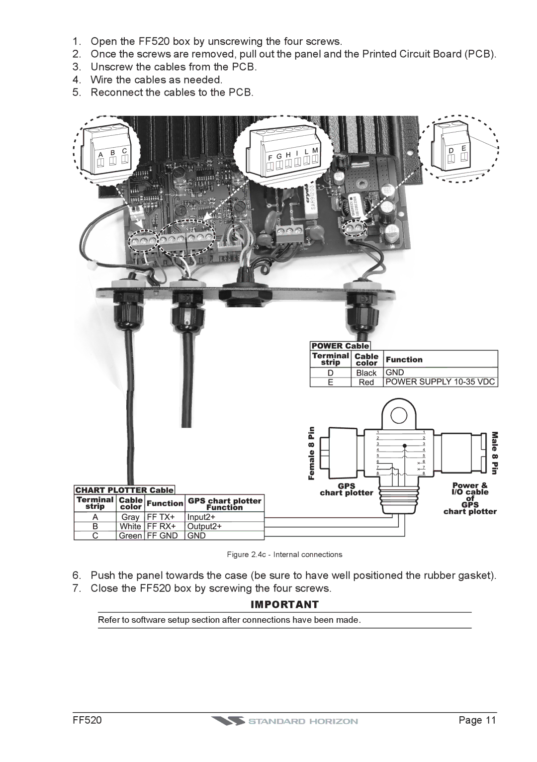
3.Unscrew the cables from the PCB.
4.Wire the cables as needed.
5.Reconnect the cables to the PCB.
Figure 2.4c - Internal connections
6.Push the panel towards the case (be sure to have well positioned the rubber gasket).
7.Close the FF520 box by screwing the four screws.
IMPORTANT
Refer to software setup section after connections have been made.
FF520 |
| Page 11 |
|
