
LC24-15 specifications
Star Micronics LC24-15 is a robust and versatile impact dot matrix printer designed specifically for applications that require high-volume printing with reliability and efficiency. This printer is particularly well-suited for environments such as retail, manufacturing, and logistics, where printing invoices, tickets, and reports is a routine task.One of the key features of the LC24-15 is its high-speed printing capability. It offers a print speed of up to 550 characters per second, allowing businesses to process large quantities of documents quickly. This efficiency is supported by its 24-pin print head, which delivers crisp and clear text and graphics, making it an excellent choice for applications requiring sharp output.
The LC24-15 supports a variety of paper sizes and types, accommodating multi-part forms and labels effortlessly. It can print on multiple copies simultaneously, making it ideal for creating invoices or shipping documents where duplicates are necessary. The printer's reliable paper handling is complemented by a built-in automatic paper loading system that simplifies the changeover between different paper types.
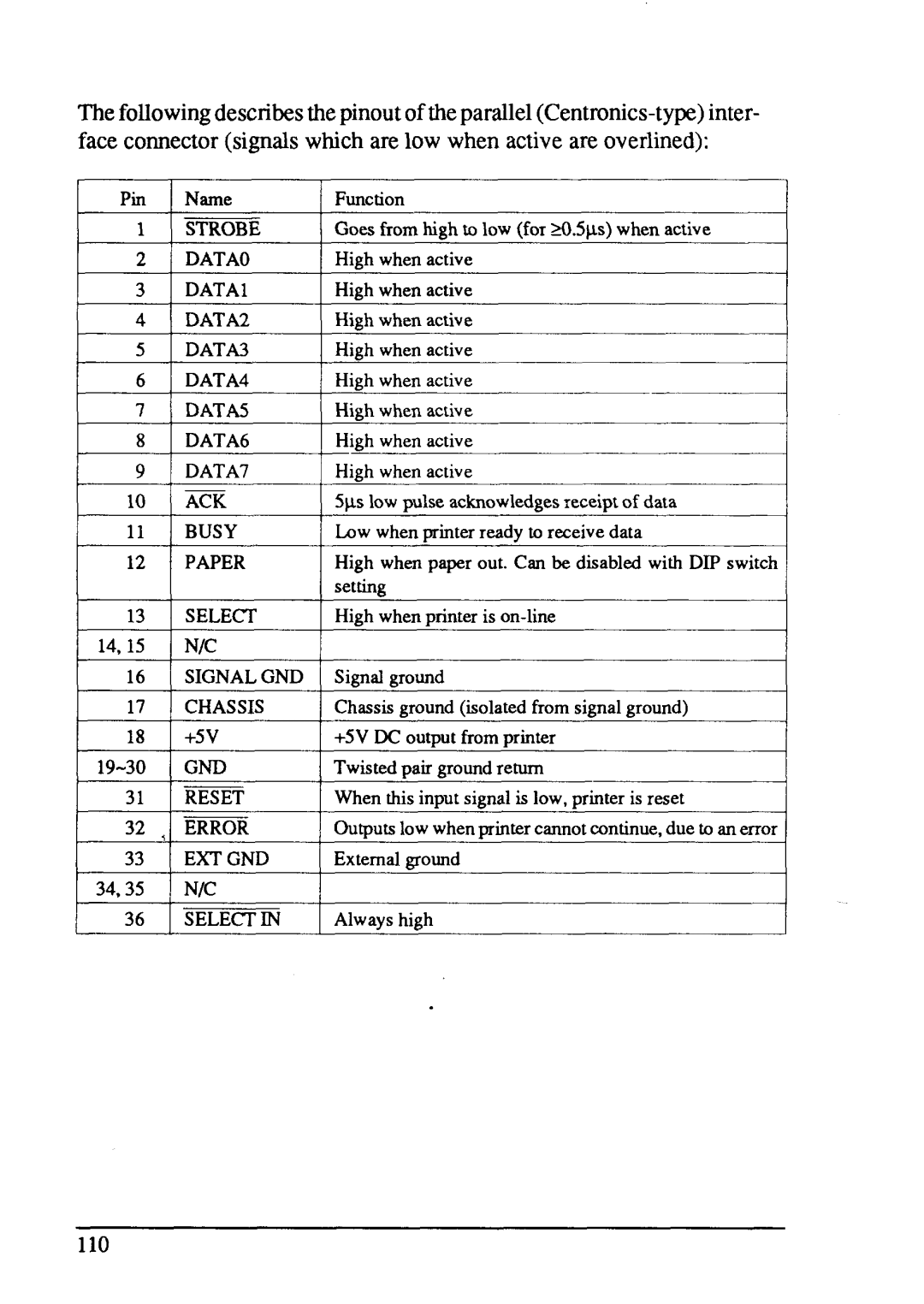
In terms of connectivity, the LC24-15 offers several ports, including parallel, serial, and USB interfaces, ensuring compatibility with various systems and devices. This flexibility allows businesses to integrate the printer into their existing workflow seamlessly. Additionally, the LC24-15 is designed with user-friendly features, such as easy controls, which facilitate quick setup and operation, reducing downtime and enhancing productivity.
Further enhancing its versatility, the LC24-15 incorporates advanced technologies such as a high-durability ribbon that extends the life of the consumables, thereby lowering operating costs. The printer's energy-efficient design also ensures lower power consumption compared to traditional printers, making it an eco-friendly choice for businesses looking to reduce their environmental impact.
Overall, the Star Micronics LC24-15 stands out in its category with a blend of speed, reliability, and user-friendliness. Whether for point of sale purposes or industrial applications, it provides the necessary features and performance that businesses demand in high-volume printing environments, making it a trusted choice for many organizations.