INSTALLATION INSTRUCTIONS
INSTALLATION
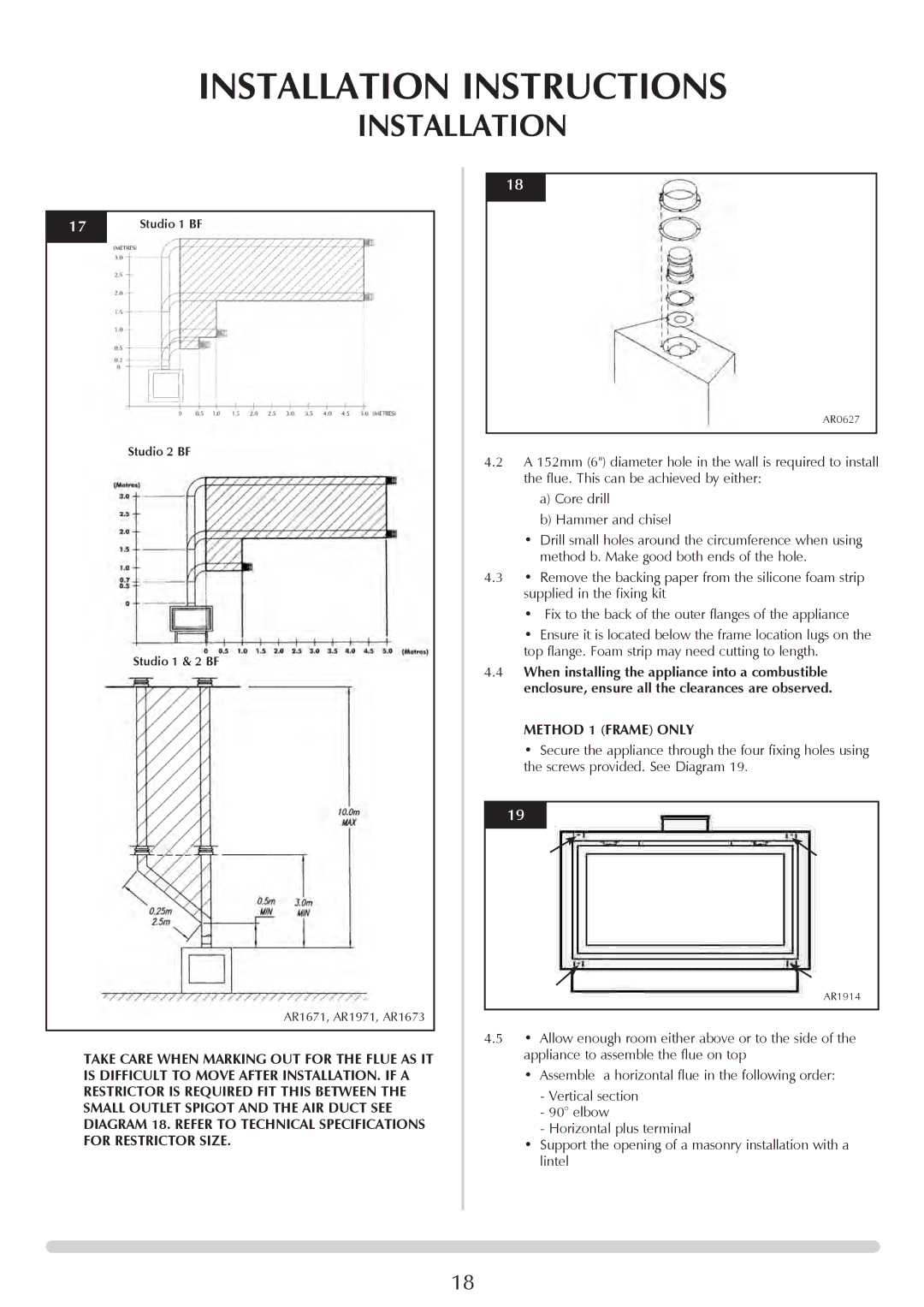
17Studio 1 BF
Studio 2 BF
Studio 1 & 2 BF
AR1671, AR1971, AR1673
TAKE CARE WHEN MARKING OUT FOR THE FLUE AS IT IS DIFFICULT TO MOVE AFTER INSTALLATION. IF A RESTRICTOR IS REQUIRED FIT THIS BETWEEN THE SMALL OUTLET SPIGOT AND THE AIR DUCT SEE DIAGRAM 18. REFER TO TECHNICAL SPECIFICATIONS FOR RESTRICTOR SIZE.
18
AR0627
4.2A 152mm (6") diameter hole in the wall is required to install the flue. This can be achieved by either:
a)Core drill
b)Hammer and chisel
•Drill small holes around the circumference when using method b. Make good both ends of the hole.
4.3• Remove the backing paper from the silicone foam strip supplied in the fixing kit
•Fix to the back of the outer flanges of the appliance
•Ensure it is located below the frame location lugs on the top flange. Foam strip may need cutting to length.
4.4When installing the appliance into a combustible enclosure, ensure all the clearances are observed.
METHOD 1 (FRAME) ONLY
•Secure the appliance through the four fixing holes using the screws provided. See Diagram 19.
19
AR1914
4.5• Allow enough room either above or to the side of the appliance to assemble the flue on top
•Assemble a horizontal flue in the following order:
-Vertical section
-90° elbow
-Horizontal plus terminal
•Support the opening of a masonry installation with a lintel
18