INSTALLATION INSTRUCTIONS
INSTALLATION
13
AR1905
3.3STUD WORK INSTALLATION METHOD 2 (EDGE)
For this
There is an optional Studio Edge Fixing Kit available for installing the fire without a frame. STUDIO 1BF CODE No. 8727BFFK01 STUDIO 2BF CODE No. 8727BFFK02 Using the fixing kit:
•Fit the two side and bottom channels to the front flange of the fire, Diagram 14. There is a deliberate gap at the top for convected heat
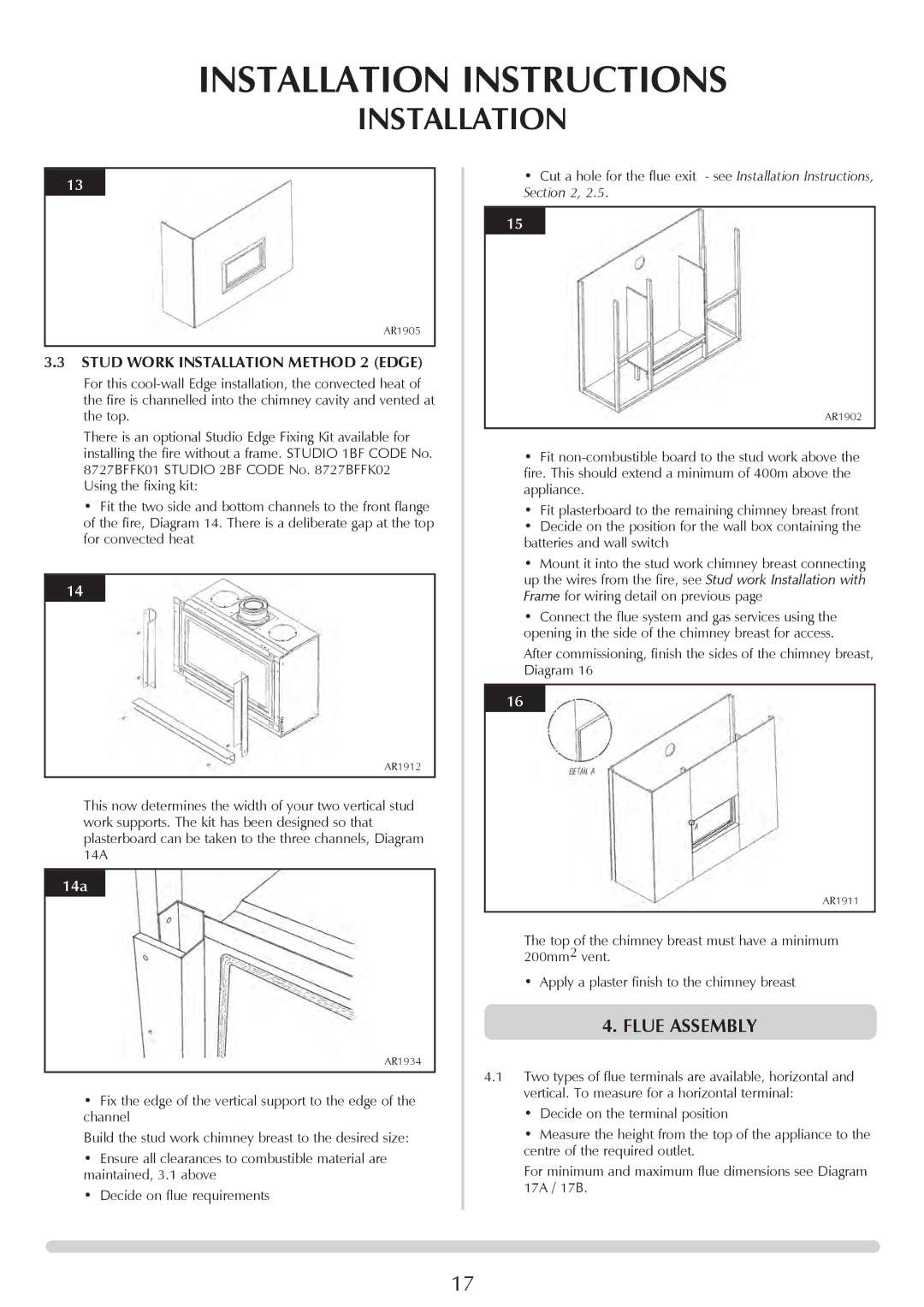
14
AR1912
This now determines the width of your two vertical stud work supports. The kit has been designed so that plasterboard can be taken to the three channels, Diagram 14A
14a
AR1934
•Fix the edge of the vertical support to the edge of the channel
Build the stud work chimney breast to the desired size:
•Ensure all clearances to combustible material are maintained, 3.1 above
•Decide on flue requirements
•Cut a hole for the flue exit - see Installation Instructions, Section 2, 2.5.
15
AR1902
•Fit
•Fit plasterboard to the remaining chimney breast front
•Decide on the position for the wall box containing the batteries and wall switch
•Mount it into the stud work chimney breast connecting up the wires from the fire, see Stud work Installation with Frame for wiring detail on previous page
•Connect the flue system and gas services using the opening in the side of the chimney breast for access.
After commissioning, finish the sides of the chimney breast, Diagram 16
16
AR1911
The top of the chimney breast must have a minimum 200mm2 vent.
•Apply a plaster finish to the chimney breast
4.FLUE ASSEMBLY
4.1Two types of flue terminals are available, horizontal and vertical. To measure for a horizontal terminal:
•Decide on the terminal position
•Measure the height from the top of the appliance to the centre of the required outlet.
For minimum and maximum flue dimensions see Diagram 17A / 17B.
17