A+ SERVER
Unit Identifier Button
In addition to the UID (Unit Identifier) button on the rear I/O panel, there is another UID button located on the control panel. When you push either UID button, both Rear UID and Front Panel UID Indicators will illumi- nate. Push either button again to turn off both indicators. These UID indicators provide easy identification of a system unit that may be in need of service.
IPMB
A System Management Bus header for the IPMI slot is located at IPMB. Connect the appropriate cable here to use the IPMB I2C connection on your system.
Video Connector
A Video (VGA) connector is located below the COM Port on the IO backplane. This connector is used to provide video and CRT display.
Compact Flash Card PWR Connector
A Compact Flash Card Power Connector is located at JWF1. For the Compact Flash Card to work properly, you will need to en- able with JCF1 and connect a Compact Flash Card power cable to JWF1 first.
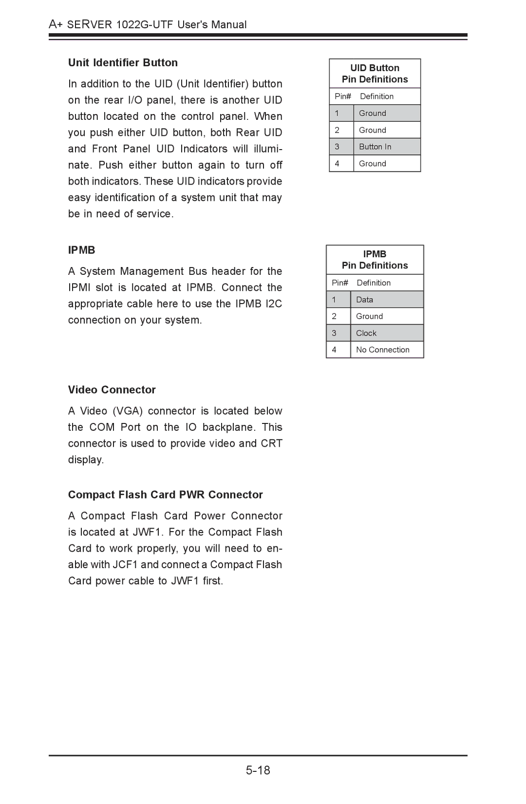
UID Button
Pin Definitions
Pin# Definition
1Ground
2Ground
3Button In
4Ground
IPMB
Pin Definitions
Pin# Definition
1Data
2Ground
3Clock
4No Connection