A+ SERVER
See the Connector Definitions section in this chapter for details and pin descrip- tions of JF1.
Figure 5-1. Front Control Panel Header Pins (JF1)
20 19 Ground ![]()
![]()
x (key)
Power LED
HDD LED
NIC1 (Link) LED
NIC2 (Link) LED
OH/Fan Fail LED
Power Fail LED
Ground
Ground
2 1
NMI
x(key) Vcc Vcc
NIC1 (Activity) LED NIC2 (Activity) LED Vcc
Vcc Reset Power
5-4 I/O Ports
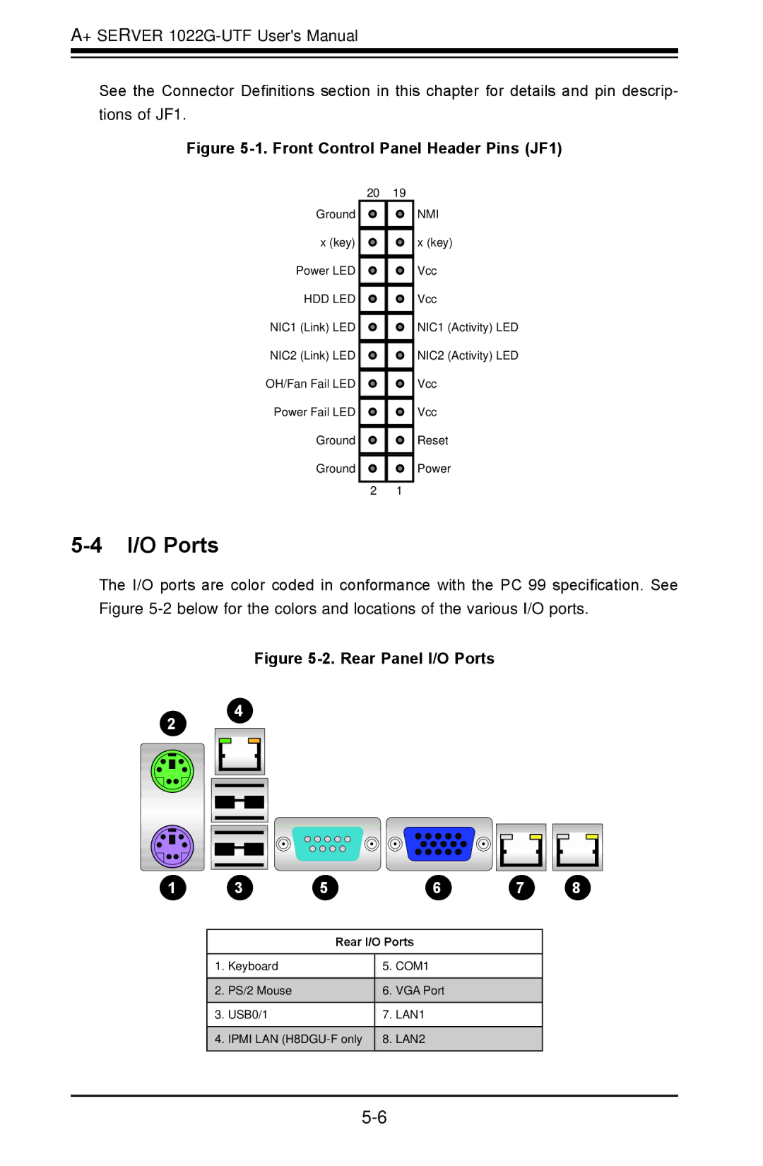
The I/O ports are color coded in conformance with the PC 99 specification. See Figure
Figure 5-2. Rear Panel I/O Ports
12 14
1 | 1 | 1 | 1 | 1 | 1 |
1 | 3 | 5 | 6 | 7 | 8 |
| Rear I/O Ports | ||
|
|
|
|
1. | Keyboard | 5. | COM1 |
|
|
|
|
2. | PS/2 Mouse | 6. | VGA Port |
|
|
|
|
3. | USB0/1 | 7. | LAN1 |
|
|
|
|
4. | IPMI LAN | 8. | LAN2 |
|
|
|
|