SUPERSERVER
Fan Headers
The
Power Fault
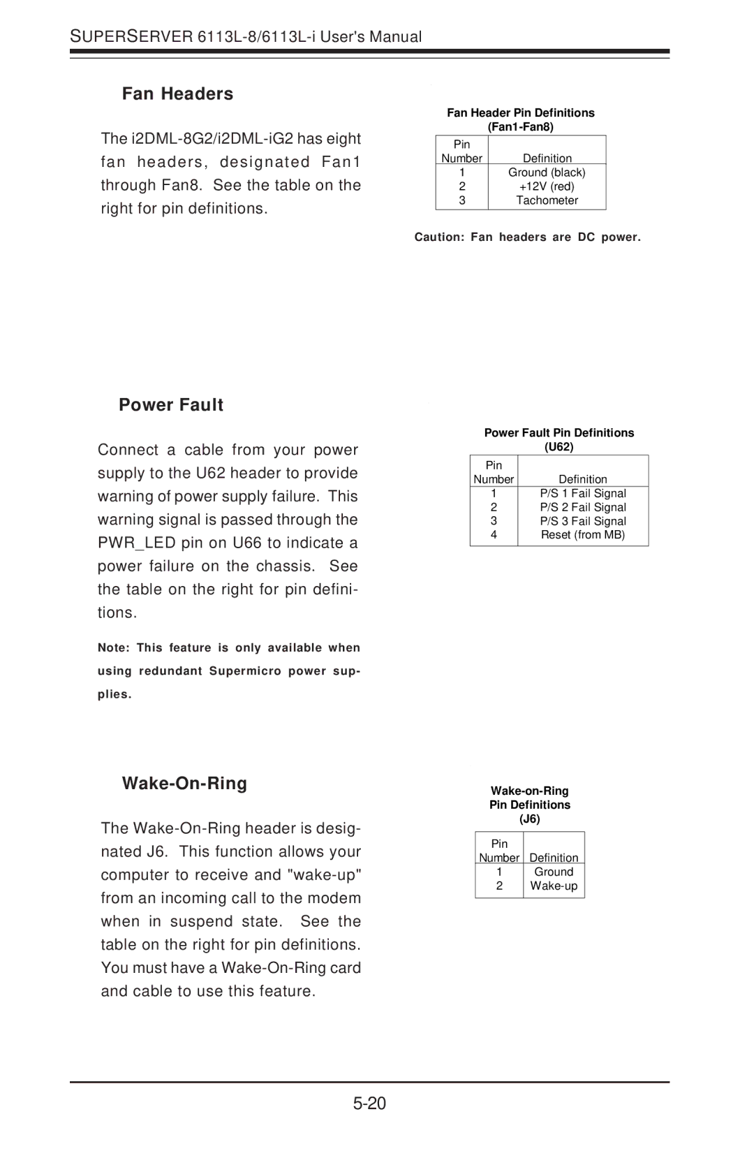
Connect a cable from your power supply to the U62 header to provide warning of power supply failure. This warning signal is passed through the PWR_LED pin on U66 to indicate a power failure on the chassis. See the table on the right for pin defini- tions.
Note: This feature is only available when
using redundant Supermicro power sup-
plies.
Wake-On-Ring
The
Fan Header Pin Definitions
Pin | Definition |
Number |
1Ground (black)
2+12V (red)
3Tachometer
Caution: Fan headers are DC power.
Power Fault Pin Definitions
(U62)
Pin |
|
Number | Definition |
1 | P/S 1 Fail Signal |
2 | P/S 2 Fail Signal |
3 | P/S 3 Fail Signal |
4 | Reset (from MB) |
|
|
Pin Definitions
(J6)
Pin
Number Definition
1Ground
2