SUPERSERVER
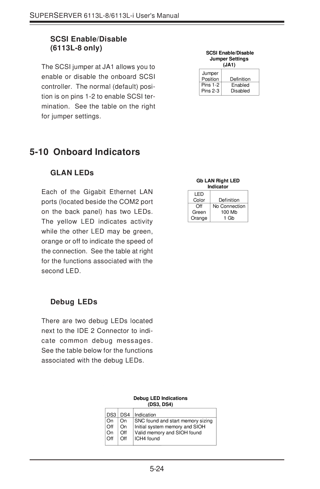
SCSI Enable/Disable (6113L-8 only)
The SCSI jumper at JA1 allows you to enable or disable the onboard SCSI controller. The normal (default) posi- tion is on pins
SCSI Enable/Disable
Jumper Settings
(JA1)
Jumper |
|
Position | Definition |
Pins | Enabled |
Pins | Disabled |
5-10 Onboard Indicators
GLAN LEDs
Each of the Gigabit Ethernet LAN ports (located beside the COM2 port on the back panel) has two LEDs. The yellow LED indicates activity while the other LED may be green, orange or off to indicate the speed of the connection. See the table at right for the functions associated with the second LED.
Gb LAN Right LED
Indicator
LED |
|
Color | Definition |
Off | No Connection |
Green | 100 Mb |
Orange | 1 Gb |
Debug LEDs
There are two debug LEDs located next to the IDE 2 Connector to indi- cate common debug messages. See the table below for the functions associated with the debug LEDs.
|
| Debug LED Indications |
|
| (DS3, DS4) |
DS3 | DS4 | Indication |
On | On | SNC found and start memory sizing |
Off | On | Initial system memory and SIOH |
On | Off | Valid memory and SIOH found |
Off | Off | ICH4 found |
|
|
|