SUPERSERVER
5-7 Serverboard Details
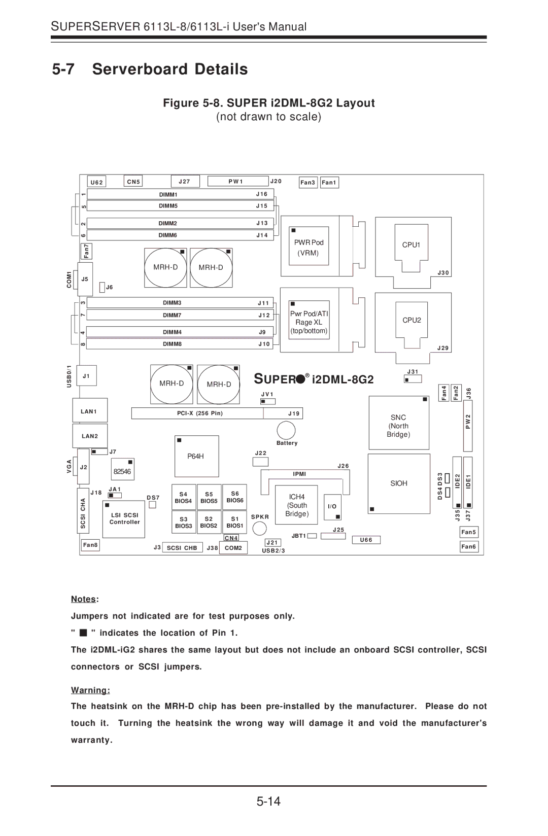
Figure 5-8. SUPER i2DML-8G2 Layout
(not drawn to scale)
U62 |
CN5 |
| J 2 7 |
| P W 1 | J 2 0 | Fan3 | Fan1 |
|
|
| 1 |
| ||
|
|
|
|
| 5 |
|
|
|
|
|
|
| |
|
|
| 2 |
| ||
|
|
|
| |||
|
|
|
|
| 6 |
|
|
|
|
|
|
| |
|
|
|
|
|
| |
|
|
|
|
| Fan7 | |
COM1 |
|
|
|
|
|
|
|
|
|
| J5 | ||
|
|
|
| |||
|
|
|
|
|
| |
|
|
|
|
|
|
|
|
|
| 3 |
| ||
|
|
| 7 |
| ||
|
| 4 |
| |||
|
|
| ||||
|
|
| 8 |
| ||
|
|
|
| |||
|
|
|
|
|
|
|
DIMM1 | J 1 6 |
DIMM5 | J 1 5 |
DIMM2 | J 1 3 |
DIMM6 | J 1 4 |
|
|
| ||
J6 |
|
|
|
|
DIMM3 |
|
| J 1 1 | |
|
|
| ||
| DIMM7 |
|
| J 1 2 |
| DIMM4 |
|
| J9 |
| DIMM8 |
|
| J 1 0 |
PWR Pod (VRM)
Pwr Pod/ATI
Rage XL
(top/bottom)
CPU1
CPU2
J 3 0
J 2 9
B0/1 | J1 |
| |
US |
|
| |
|
|
|
|
|
| LAN1 | |
|
|
| |
|
|
| |
|
| LAN2 | |
|
| SUPER ® | ||||
|
|
|
| J V 1 | ||
|
|
|
|
|
|
|
|
|
|
|
|
|
|
|
| J 1 9 |
| |||
J 3 1
SNC
(North
Bridge)
Fan4 | Fan2 | J3 6 |
|
| P W 2 |
G A | J2 |
V |
|
| J 1 8 |
| SCSI CHA |
Fan8
J7
82546
JA1
LSI SCSI
Controller
|
|
|
|
|
|
|
|
|
|
|
|
|
|
| Battery |
|
| ||||
|
|
| P64H |
|
|
| J 2 2 |
|
|
|
|
| |||||||||
|
|
|
|
|
|
|
|
|
|
|
|
|
|
|
|
|
|
|
| J 2 6 | |
|
|
|
|
|
|
|
|
|
|
|
|
|
|
|
|
|
|
|
| ||
|
|
|
|
|
|
|
|
|
|
|
|
|
|
|
|
| IPMI |
|
| ||
|
|
|
|
|
|
|
|
|
|
|
|
|
|
|
|
|
|
|
|
|
|
D S 7 |
| S 4 |
| S5 | S6 |
|
|
|
|
|
|
| ICH4 |
|
|
|
| ||||
|
| BIOS4 | BIOS5 | BIOS6 |
|
|
|
|
|
|
| (South |
|
| I/O |
| |||||
|
|
|
|
|
|
|
|
|
|
|
|
|
|
|
|
|
|
| |||
|
|
| S3 |
| S2 | S1 | S P K R |
|
| Bridge) |
|
|
| ||||||||
|
|
|
|
|
|
|
|
|
| ||||||||||||
|
|
| BIOS3 | BIOS2 | BIOS1 |
|
|
|
|
|
|
|
|
|
| J 2 5 | |||||
|
|
|
|
|
|
|
|
| JBT1 |
| |||||||||||
|
|
|
|
|
|
|
|
|
|
|
|
|
|
|
|
|
| ||||
|
|
|
|
|
|
|
| CN4 |
|
|
|
|
|
|
|
|
|
|
| ||
J3 | SCSI CHB |
| J 3 8 |
| COM2 |
|
|
| J 2 1 |
|
|
|
|
|
| ||||||
|
|
|
| USB2/3 |
|
|
|
|
| ||||||||||||
|
|
|
|
|
|
|
|
|
|
|
|
|
|
|
|
| |||||
U66
SIOH
D S 3 | DE2 | DE1 |
4 | I | I |
D S |
|
|
|
|
|
| J 3 5 | J 3 7 |
Fan5
Fan6
Notes:
Jumpers not indicated are for test purposes only. " ![]()
![]() " indicates the location of Pin 1.
" indicates the location of Pin 1.
The
Warning:
The heatsink on the