2 |
30.Data from Serial Bus Address 31 in the Primary PLC is the "preferred" data. The GDB control strategy must be used and all redundant Genius outputs must be transferred from the active to the backup unit.
Each dual bus can have up to 30 additional Genius devices connected to it. One Serial Bus Address must be reserved for a
As a safety feature, a watchdog timer protects each Genius I/O link. The bus controller periodically resets this timer. If the timer ever expires, the bus controller stops functioning and its Channel OK LED turns off. If this happens in a Dual Bus Genius network of a CPU Redundant system, the paired GBC in the remote CPU drives the Genius I/O blocks. If the remote unit GBC is not available, the BSMs switch busses and use outputs from the other bus. The cause of the failure must be remedied to
Connectors
The Bus Controller has a
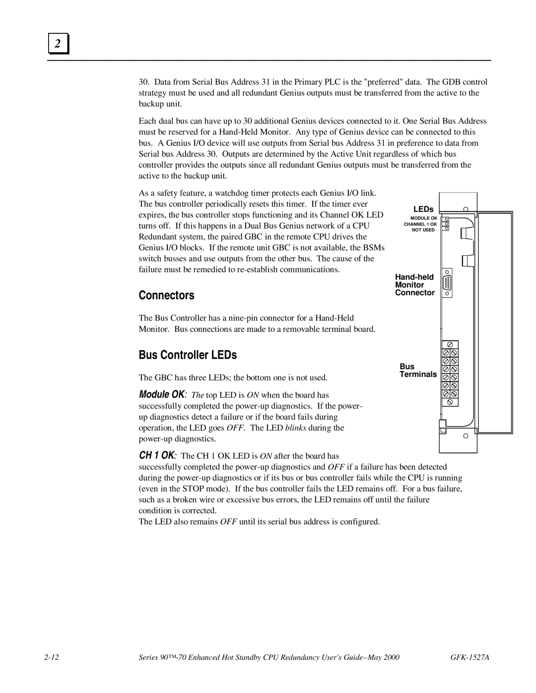
Bus Controller LEDs
The GBC has three LEDs; the bottom one is not used.
Module OK: The top LED is ON when the board has successfully completed the
LEDs |
MODULE OK |
CHANNEL 1 OK |
NOT USED |
Monitor |
Connector |
Bus |
Terminals |
CH 1 OK: The CH 1 OK LED is ON after the board has
successfully completed the
The LED also remains OFF until its serial bus address is configured.
Series |