2 |
CPU Features
Memory Protect Keyswitch
The Memory Protect keyswitch can be used to manually lock program and configuration data from access by a remote programmer (serial or Ethernet). When the key is in the ON position, program and configuration data can only be changed by a programmer connected to the Bus Transmitter Module.
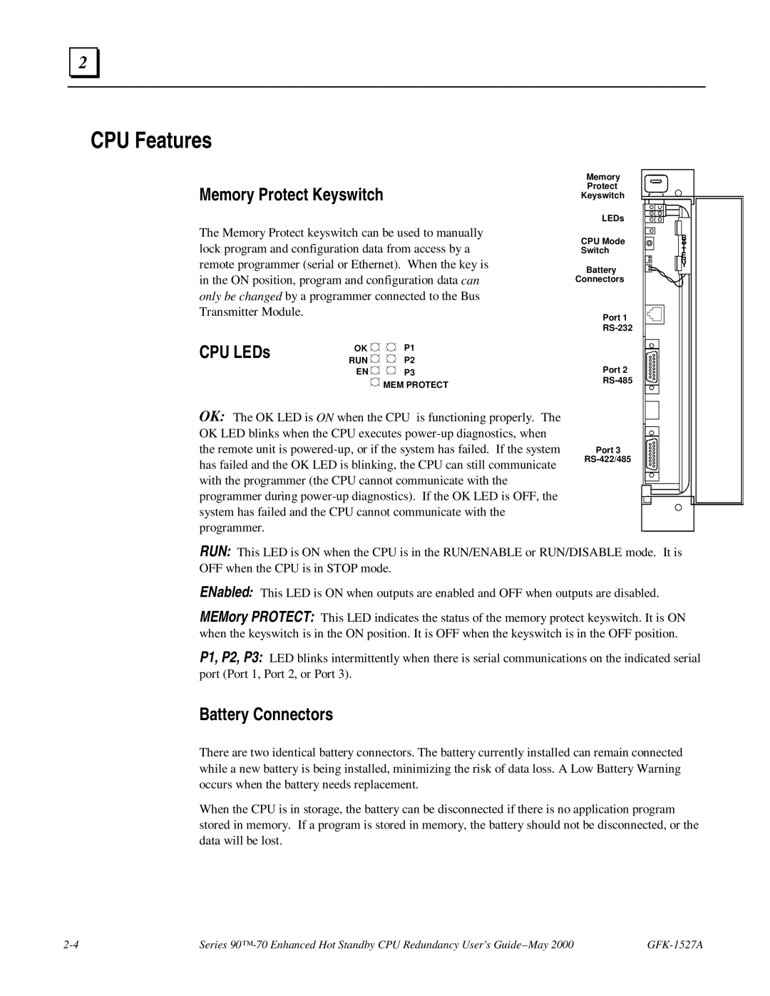
CPU LEDs | OK | P1 | |
RUN | P2 | ||
| |||
| EN | P3 |
![]() MEM PROTECT
MEM PROTECT
OK: The OK LED is ON when the CPU is functioning properly. The OK LED blinks when the CPU executes
Memory |
|
Protect |
|
Keyswitch |
|
LEDs |
|
CPU Mode | B |
A | |
Switch | T |
T | |
| E |
| R |
Battery | Y |
| |
Connectors |
|
Port 1 |
|
| |
Port 2 |
|
| |
Port 3 |
|
|
RUN: This LED is ON when the CPU is in the RUN/ENABLE or RUN/DISABLE mode. It is OFF when the CPU is in STOP mode.
ENabled: This LED is ON when outputs are enabled and OFF when outputs are disabled.
MEMory PROTECT: This LED indicates the status of the memory protect keyswitch. It is ON when the keyswitch is in the ON position. It is OFF when the keyswitch is in the OFF position.
P1, P2, P3: LED blinks intermittently when there is serial communications on the indicated serial port (Port 1, Port 2, or Port 3).
Battery Connectors
There are two identical battery connectors. The battery currently installed can remain connected while a new battery is being installed, minimizing the risk of data loss. A Low Battery Warning occurs when the battery needs replacement.
When the CPU is in storage, the battery can be disconnected if there is no application program stored in memory. If a program is stored in memory, the battery should not be disconnected, or the data will be lost.
Series |