4 |
Switching Control to the Backup Unit
Control switches from the active unit to the backup unit if:
1. the active unit has a failure;
2. the pushbutton switch on the Redundancy Communications Module is pressed;
3. a switch is commanded from the application program.
4. the active unit is placed in Stop mode or powered off.
Switching Times
The amount of time needed to switch control from the active unit to the backup unit depends on the reason for the switch.
If the active PLC CPU fails or loses power, switching occurs after the backup unit determines that the active unit failed to rendezvous at the synchronization point. Failure to rendezvous may take up to 2 failwait timeouts (one for each link) to determine. Control does not transfer until both Redundancy Communications links have been tried unsuccessfully.
If the RCM switch is pressed, or if the application program commands a role switch (see below) or if the CPU detects a fault, the switch occurs at the start of the next sweep. The delay is up to 1 sweep. There may be an input and an output scan after fault detection. A control takeover due to failure or loss of power can occur at any time. However, a manual role switch may not occur within 10 seconds of a previous manual role switch.
Commanding a Role Switch from the Application Program (SVCREQ #26)
The application program can use SVCREQ #26 to command a role switch between the redundant CPUs (active to backup and backup to active). The switch occurs on the next sweep if the units are synchronized.
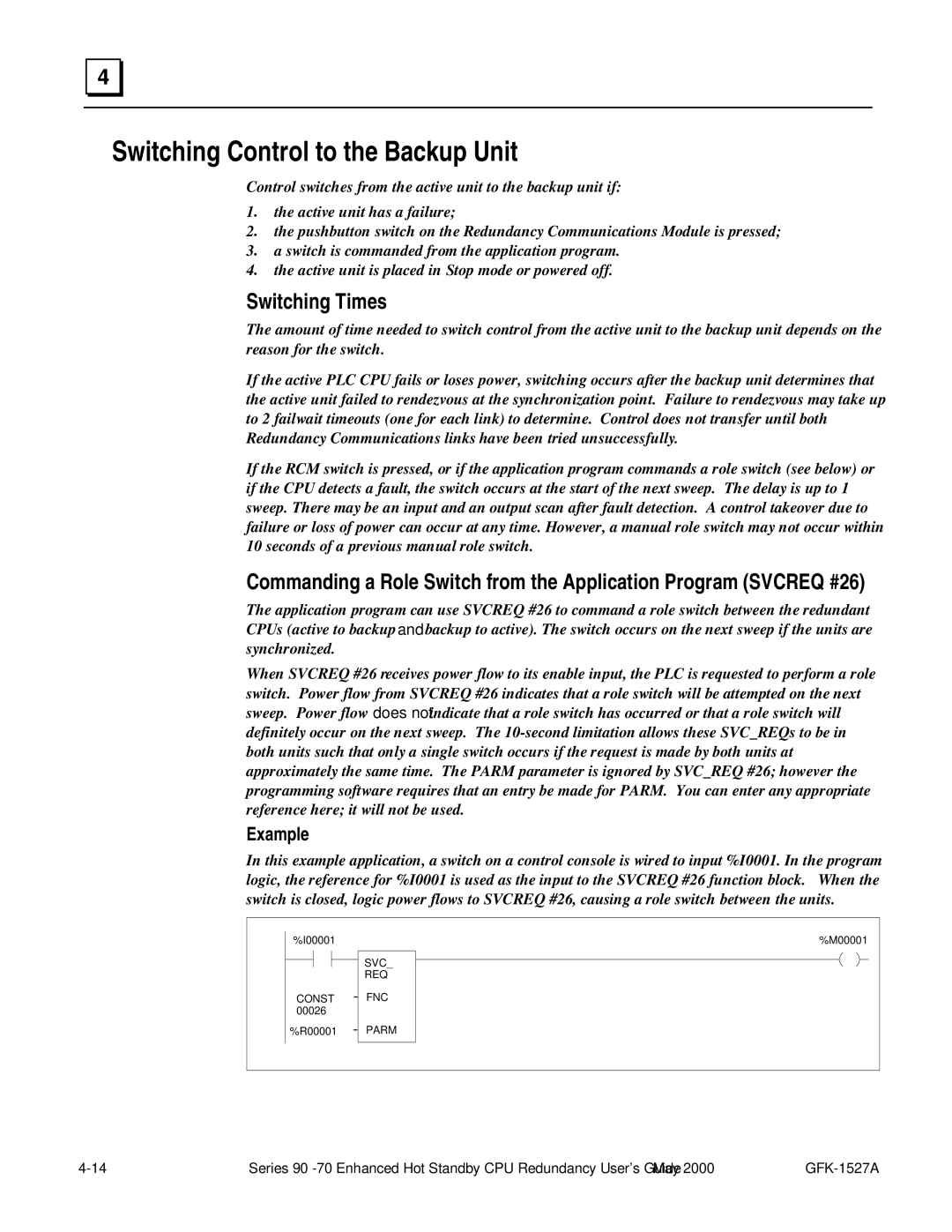
When SVCREQ #26 receives power flow to its enable input, the PLC is requested to perform a role switch. Power flow from SVCREQ #26 indicates that a role switch will be attempted on the next sweep. Power flow does not indicate that a role switch has occurred or that a role switch will definitely occur on the next sweep. The
Example
In this example application, a switch on a control console is wired to input %I0001. In the program logic, the reference for %I0001 is used as the input to the SVCREQ #26 function block. When the switch is closed, logic power flows to SVCREQ #26, causing a role switch between the units.
%I00001 |
| %M00001 |
|
| SVC_ |
|
| REQ |
CONST | - | FNC |
00026 |
|
|
%R00001 | - | PARM |
Series |
