4 |
Miscellaneous Operation Information
Timer and PID Function Blocks
Timer and PID function blocks remain in lock step between two synchronized units provided:
A.Enabling logic is identical on both units. This includes power flow, frequency of calling
B.The
C.Reference registers (3 for timers, 40 for PID) and reset references for each timer and PID function block are included in the data transfer lists.
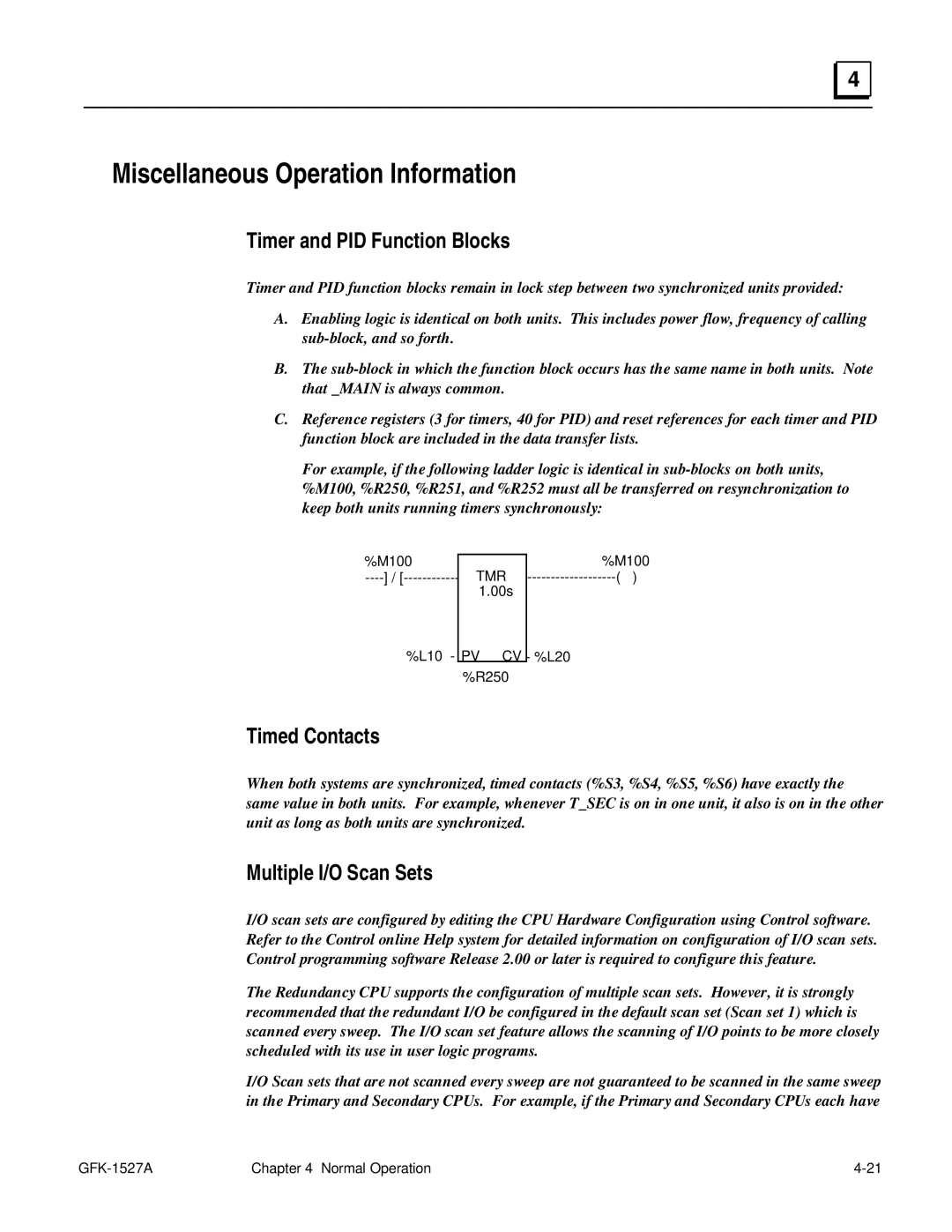
For example, if the following ladder logic is identical in
%M100 | TMR |
1.00s
%M100
-------------------( )
%L10 - PV CV - %L20 %R250
Timed Contacts
When both systems are synchronized, timed contacts (%S3, %S4, %S5, %S6) have exactly the same value in both units. For example, whenever T_SEC is on in one unit, it also is on in the other unit as long as both units are synchronized.
Multiple I/O Scan Sets
I/O scan sets are configured by editing the CPU Hardware Configuration using Control software. Refer to the Control online Help system for detailed information on configuration of I/O scan sets. Control programming software Release 2.00 or later is required to configure this feature.
The Redundancy CPU supports the configuration of multiple scan sets. However, it is strongly recommended that the redundant I/O be configured in the default scan set (Scan set 1) which is scanned every sweep. The I/O scan set feature allows the scanning of I/O points to be more closely scheduled with its use in user logic programs.
I/O Scan sets that are not scanned every sweep are not guaranteed to be scanned in the same sweep in the Primary and Secondary CPUs. For example, if the Primary and Secondary CPUs each have
| Chapter 4 Normal Operation |