2 |
Bus Receiver Module
The Bus Receiver Module (BRM), catalog number IC697BEM711, is the expansion rack interface to the I/O bus. The Bus Receiver Module connects to a Bus Transmitter Module in rack 0 or to a Bus Receiver Module in the previous rack via a parallel I/O bus cable.
In a CPU Redundancy system with expansion racks, the last bus connection is to a Redundancy Communications Module, as explained previously.
Connectors
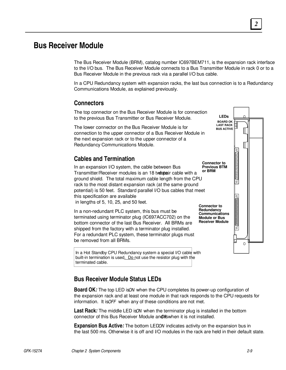
The top connector on the Bus Receiver Module is for connection to the previous Bus Transmitter or Bus Receiver Module.
The lower connector on the Bus Receiver Module is for connection to the upper connector of a Bus Receiver Module in the next expansion rack or to the upper connector of a Redundancy Communications Module.
LEDs
BOARD OK ![]()
![]()
![]()
![]()
![]()
![]() LAST RACK
LAST RACK![]() BUS ACTIVE
BUS ACTIVE
Cables and Termination
In an expansion I/O system, the cable between Bus Transmitter/Receiver modules is an 18
in lengths of 5, 10, 25, and 50 feet.
In a
In a Hot Standby CPU Redundancy system a special I/O cable with
Connector to Previous BTM or BRM
Connector to Redundancy Communications Module or Bus Receiver Module
Bus Receiver Module Status LEDs
Board OK: The top LED is ON when the CPU completes its
Last Rack: The middle LED is ON when the terminator plug is installed in the bottom connector of this Bus Receiver Module and is Off when it is not installed.
Expansion Bus Active: The bottom LED ON indicates activity on the expansion bus in the last 500 ms. Otherwise it is off and I/O modules in the rack are held in their default state.
Chapter 2 System Components |