4 |
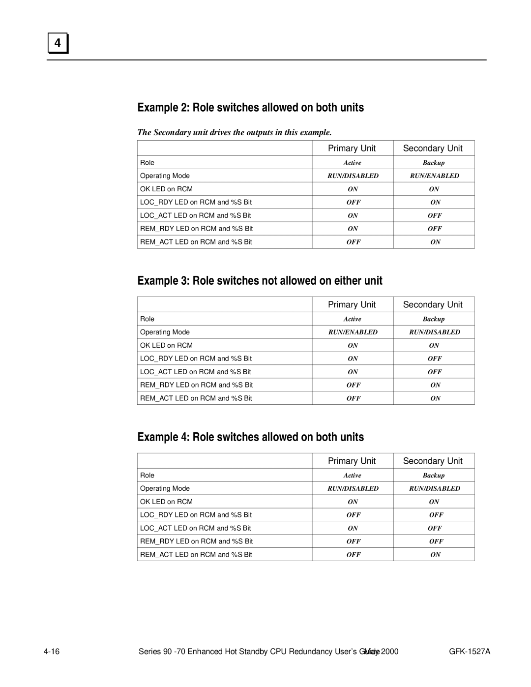
Example 2: Role switches allowed on both units
The Secondary unit drives the outputs in this example.
| Primary Unit | Secondary Unit |
|
|
|
Role | Active | Backup |
|
|
|
Operating Mode | RUN/DISABLED | RUN/ENABLED |
|
|
|
OK LED on RCM | ON | ON |
|
|
|
LOC_RDY LED on RCM and %S Bit | OFF | ON |
|
|
|
LOC_ACT LED on RCM and %S Bit | ON | OFF |
|
|
|
REM_RDY LED on RCM and %S Bit | ON | OFF |
|
|
|
REM_ACT LED on RCM and %S Bit | OFF | ON |
|
|
|
Example 3: Role switches not allowed on either unit
| Primary Unit | Secondary Unit |
|
|
|
Role | Active | Backup |
|
|
|
Operating Mode | RUN/ENABLED | RUN/DISABLED |
|
|
|
OK LED on RCM | ON | ON |
|
|
|
LOC_RDY LED on RCM and %S Bit | ON | OFF |
|
|
|
LOC_ACT LED on RCM and %S Bit | ON | OFF |
|
|
|
REM_RDY LED on RCM and %S Bit | OFF | ON |
|
|
|
REM_ACT LED on RCM and %S Bit | OFF | ON |
|
|
|
Example 4: Role switches allowed on both units
| Primary Unit | Secondary Unit |
|
|
|
Role | Active | Backup |
|
|
|
Operating Mode | RUN/DISABLED | RUN/DISABLED |
|
|
|
OK LED on RCM | ON | ON |
|
|
|
LOC_RDY LED on RCM and %S Bit | OFF | OFF |
|
|
|
LOC_ACT LED on RCM and %S Bit | ON | OFF |
|
|
|
REM_RDY LED on RCM and %S Bit | OFF | OFF |
|
|
|
REM_ACT LED on RCM and %S Bit | OFF | ON |
|
|
|
Series |