1 |
Single Bus with Floating Master: GDB Control Strategy
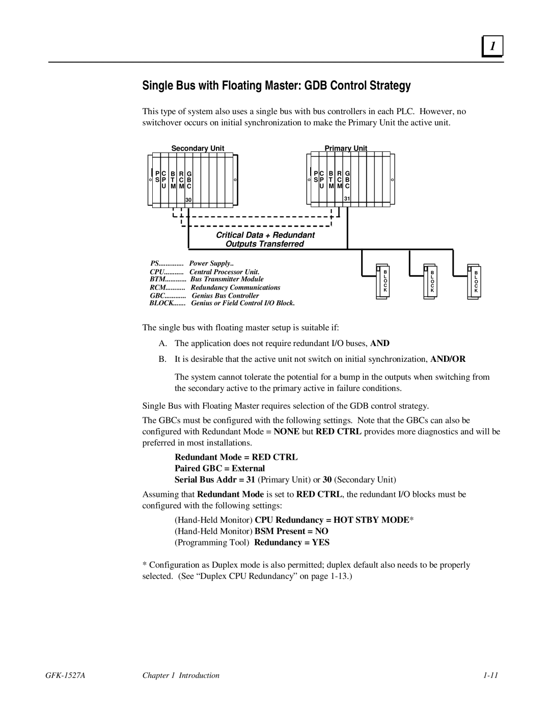
This type of system also uses a single bus with bus controllers in each PLC. However, no switchover occurs on initial synchronization to make the Primary Unit the active unit.
Secondary Unit
P C B R G
S P T C B
UM M C
30
Primary Unit
P C B R G
S P T C B
U M M C
31
Critical Data + Redundant
Outputs Transferred
PS | Power Supply.. |
|
|
|
|
|
|
|
|
|
|
|
|
|
| |
...........CPU | Central Processor Unit. |
|
|
| B |
|
|
| B |
|
|
|
|
| ||
BTM | Bus Transmitter Module |
|
| L |
|
|
| L |
|
|
|
|
| |||
| O |
|
|
| O |
|
|
|
|
| ||||||
RCM | Redundancy Communications |
|
| C |
|
|
| C |
|
|
|
|
| |||
| K |
|
|
| K |
|
|
|
|
| ||||||
GBC | Genius Bus Controller |
|
|
|
|
|
|
|
|
|
| |||||
|
|
|
|
|
|
|
|
|
|
|
|
| ||||
.......BLOCK | Genius or Field Control I/O Block. |
|
|
|
|
|
|
|
|
|
|
|
|
|
| |
B L O C K
The single bus with floating master setup is suitable if:
A.The application does not require redundant I/O buses, AND
B.It is desirable that the active unit not switch on initial synchronization, AND/OR
The system cannot tolerate the potential for a bump in the outputs when switching from the secondary active to the primary active in failure conditions.
Single Bus with Floating Master requires selection of the GDB control strategy.
The GBCs must be configured with the following settings. Note that the GBCs can also be configured with Redundant Mode = NONE but RED CTRL provides more diagnostics and will be preferred in most installations.
Redundant Mode = RED CTRL
Paired GBC = External
Serial Bus Addr = 31 (Primary Unit) or 30 (Secondary Unit)
Assuming that Redundant Mode is set to RED CTRL, the redundant I/O blocks must be configured with the following settings:
(Programming Tool) Redundancy = YES
*Configuration as Duplex mode is also permitted; duplex default also needs to be properly selected. (See “Duplex CPU Redundancy” on page
Chapter 1 Introduction |
