2 |
Bus Transmitter Module
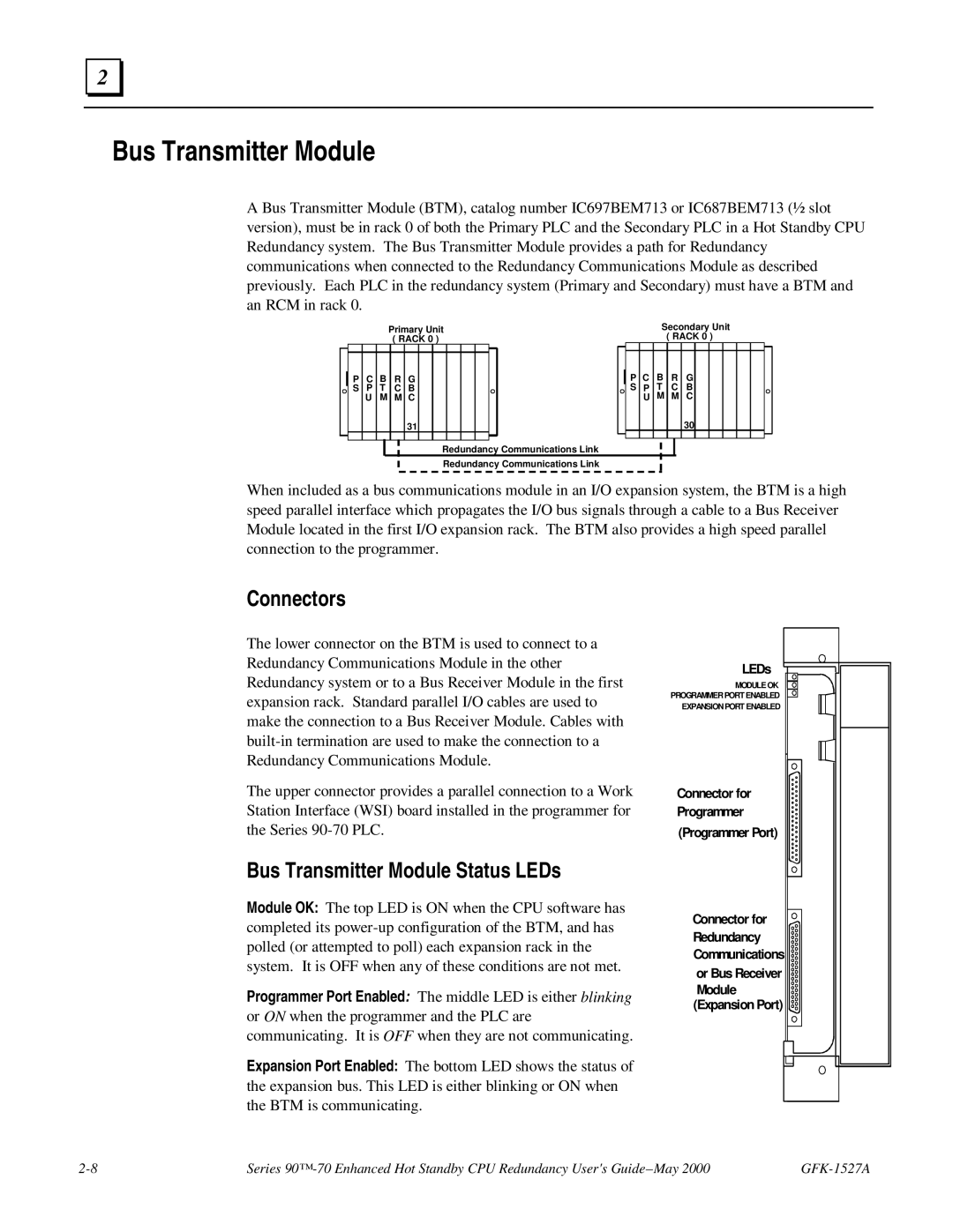
A Bus Transmitter Module (BTM), catalog number IC697BEM713 or IC687BEM713 (½ slot version), must be in rack 0 of both the Primary PLC and the Secondary PLC in a Hot Standby CPU Redundancy system. The Bus Transmitter Module provides a path for Redundancy communications when connected to the Redundancy Communications Module as described previously. Each PLC in the redundancy system (Primary and Secondary) must have a BTM and an RCM in rack 0.
|
|
|
| Primary Unit |
|
|
|
| Secondary Unit |
| |||||||||||||||
|
|
|
|
| ( RACK 0 ) |
|
|
|
| ( RACK 0 ) |
| ||||||||||||||
|
|
|
|
|
|
|
|
|
|
|
|
|
|
|
|
|
|
|
|
|
|
|
|
|
|
|
| P | C | B | R | G |
|
|
|
|
|
|
|
| P | C | B | R | G |
|
|
|
|
|
|
|
| S | P | T | C | B |
|
|
|
|
|
|
|
| S | P | T | C | B |
|
|
|
|
|
|
|
|
| U | M | M | C |
|
|
|
|
|
|
|
|
| U | M | M | C |
|
|
|
|
|
|
|
|
|
|
|
| 31 |
|
|
|
|
|
|
|
|
|
|
|
| 30 |
|
|
|
|
|
|
|
|
|
|
|
|
|
|
|
|
|
|
|
|
|
|
|
|
|
|
|
|
|
|
|
|
|
|
|
|
|
|
|
|
|
|
|
|
|
|
|
|
|
|
|
|
|
|
|
|
|
|
Redundancy Communications Link
Redundancy Communications Link
When included as a bus communications module in an I/O expansion system, the BTM is a high speed parallel interface which propagates the I/O bus signals through a cable to a Bus Receiver Module located in the first I/O expansion rack. The BTM also provides a high speed parallel connection to the programmer.
Connectors
The lower connector on the BTM is used to connect to a Redundancy Communications Module in the other Redundancy system or to a Bus Receiver Module in the first expansion rack. Standard parallel I/O cables are used to make the connection to a Bus Receiver Module. Cables with
The upper connector provides a parallel connection to a Work Station Interface (WSI) board installed in the programmer for the Series
LEDs
MODULE OK
PROGRAMMER PORT ENABLED
EXPANSION PORT ENABLED
Connector for Programmer (Programmer Port)
Bus Transmitter Module Status LEDs
Module OK: The top LED is ON when the CPU software has completed its
Programmer Port Enabled: The middle LED is either blinking or ON when the programmer and the PLC are communicating. It is OFF when they are not communicating.
Expansion Port Enabled: The bottom LED shows the status of the expansion bus. This LED is either blinking or ON when the BTM is communicating.
Connector for ![]()
![]() Redundancy Communications or Bus Receiver Module (Expansion Port)
Redundancy Communications or Bus Receiver Module (Expansion Port) ![]()
Series |