3 |
Finding the Memory Available for Application Program Storage
Shared I/O data is stored in the same memory as application program storage. To find the amount of memory available for application program(s), subtract the overall transfer data amount from the amount of memory (512K bytes for CGR772, 1024K bytes for CGR935) available for the application program.
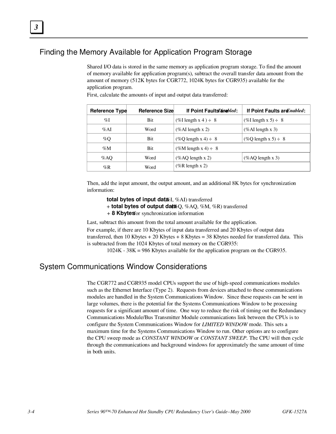
First, calculate the amounts of input and output data transferred:
Reference Type | Reference Size | If Point Faults are Disabled: | If Point Faults are Enabled: | ||
|
|
|
|
|
|
%I | Bit | (%I length x 4 ) ÷ | 8 | (%I length x 5) ÷ | 8 |
|
|
|
|
|
|
%AI | Word | (%AI length x 2) |
| (%AI length x 3) |
|
|
|
|
|
|
|
%Q | Bit | (%Q length x 4) ÷ | 8 | (%Q length x 5) ÷ | 8 |
|
|
|
|
|
|
%M | Bit | (%M length x 4) ÷ | 8 |
|
|
|
|
|
|
|
|
%AQ | Word | (%AQ length x 2) |
| (%AQ length x 3) |
|
|
|
|
|
|
|
%R | Word | (%R length x 2) |
|
|
|
|
|
|
| ||
|
|
|
|
|
|
Then, add the input amount, the output amount, and an additional 8K bytes for synchronization information:
total bytes of input data (%I, %AI) transferred
+total bytes of output data (%Q, %AQ, %M, %R) transferred
+8 Kbytes for synchronization information
Last, subtract this amount from the total amount available for the application.
For example, if there are 10 Kbytes of input data transferred and 20 Kbytes of output data transferred, then 10 Kbytes + 20 Kbytes + 8 Kbytes = 38 Kbytes needed for transferred data. This is subtracted from the 1024 Kbytes of total memory on the CGR935:
1024K - 38K = 986 Kbytes available for the application program on the CGR935.
System Communications Window Considerations
The CGR772 and CGR935 model CPUs support the use of
Series |
