1 |
Basic CPU Redundancy Setups
There are three basic CPU Redundancy setups:
Single Bus with Preferred Master
TSingle Bus with Floating Master Dual Bus with Floating Master
Single Bus with Preferred Master: GHS Control Strategy
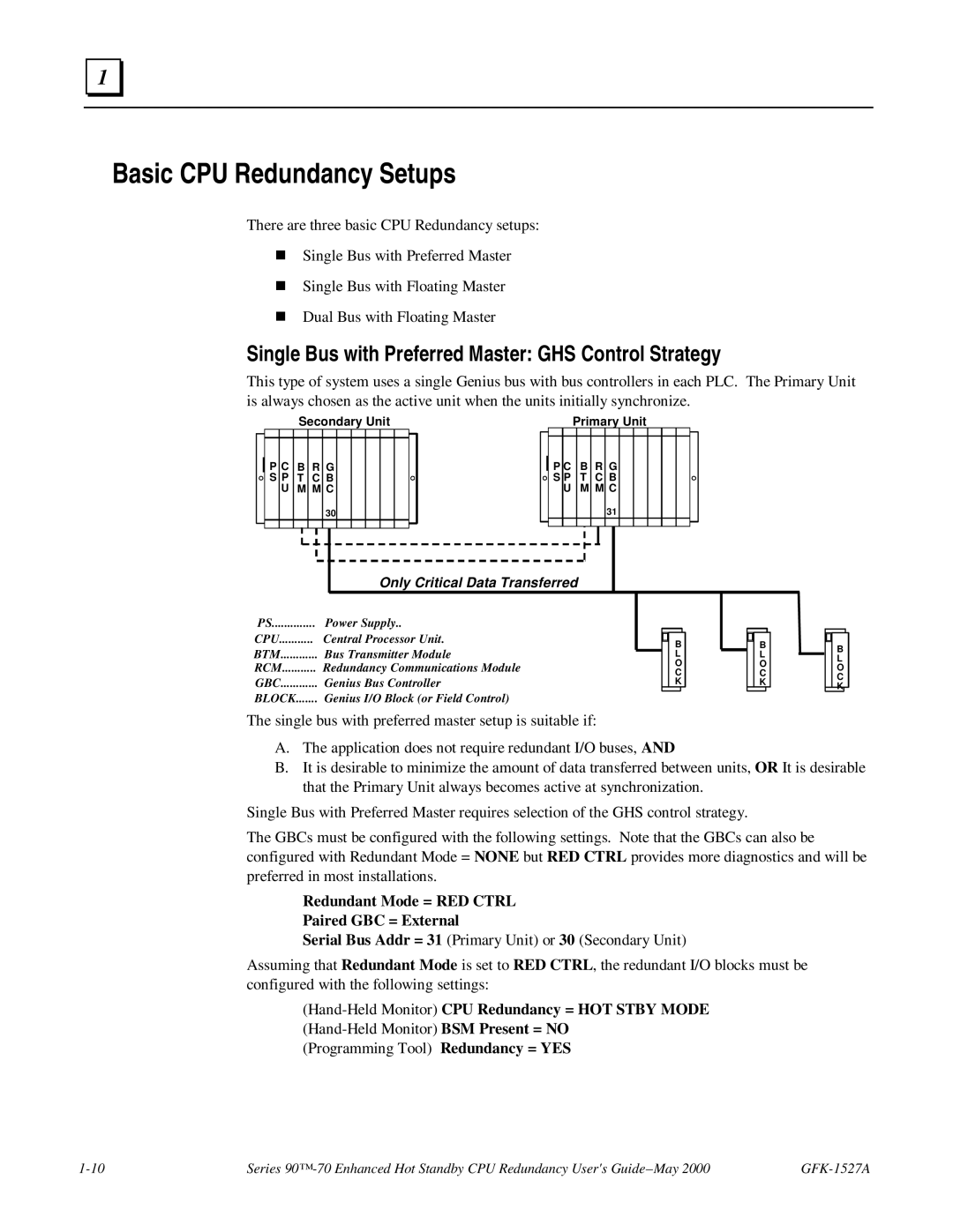
This type of system uses a single Genius bus with bus controllers in each PLC. The Primary Unit is always chosen as the active unit when the units initially synchronize.
Secondary Unit | Primary Unit |
P C B R G S P T C B
UM M C
30
P C B R G S P T C B
UM M C
31
Only Critical Data Transferred
PS | Power Supply.. |
CPU | Central Processor Unit. |
BTM | Bus Transmitter Module |
RCM | Redundancy Communications Module |
GBC | Genius Bus Controller |
BLOCK | Genius I/O Block (or Field Control) |
The single bus with preferred master setup is suitable if:
B L O C K
B L O C K
B L O C K
A.The application does not require redundant I/O buses, AND
B.It is desirable to minimize the amount of data transferred between units, OR It is desirable that the Primary Unit always becomes active at synchronization.
Single Bus with Preferred Master requires selection of the GHS control strategy.
The GBCs must be configured with the following settings. Note that the GBCs can also be configured with Redundant Mode = NONE but RED CTRL provides more diagnostics and will be preferred in most installations.
Redundant Mode = RED CTRL
Paired GBC = External
Serial Bus Addr = 31 (Primary Unit) or 30 (Secondary Unit)
Assuming that Redundant Mode is set to RED CTRL, the redundant I/O blocks must be configured with the following settings:
(Hand-Held Monitor) CPU Redundancy = HOT STBY MODE
(Programming Tool) Redundancy = YES
Series |