A |
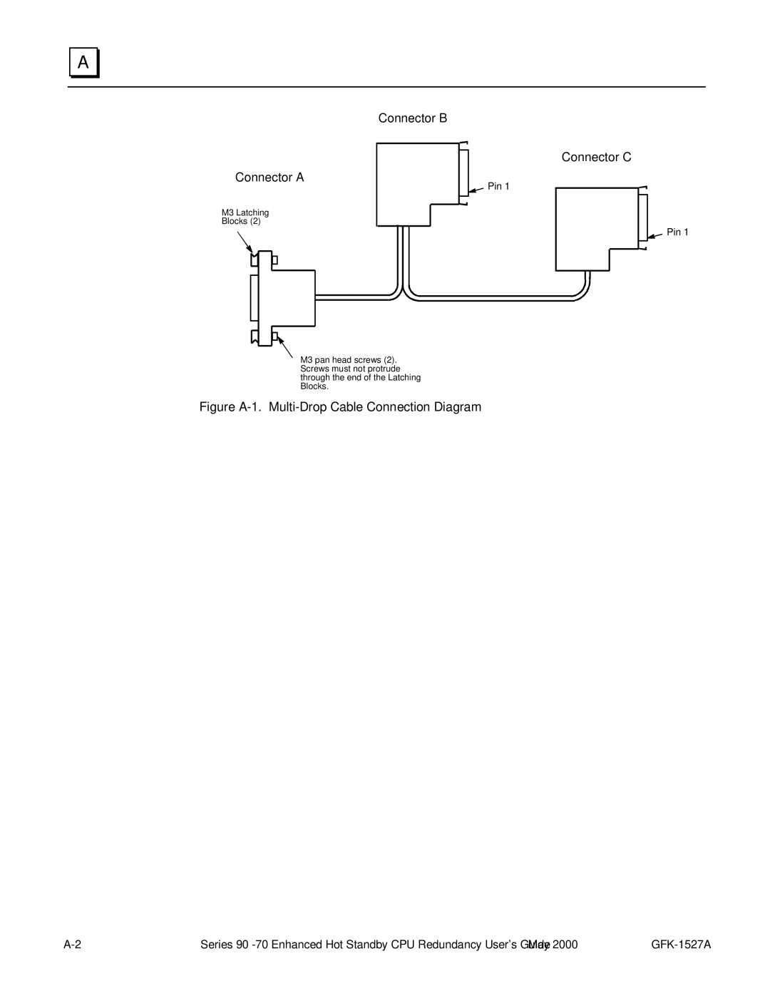
Connector A
M3 Latching
Blocks (2)
Connector B
Pin 1
Connector C
Pin 1
M3 pan head screws (2). Screws must not protrude through the end of the Latching Blocks.
Figure A-1. Multi-Drop Cable Connection Diagram
Series |