Backplane to System Board Control Connections
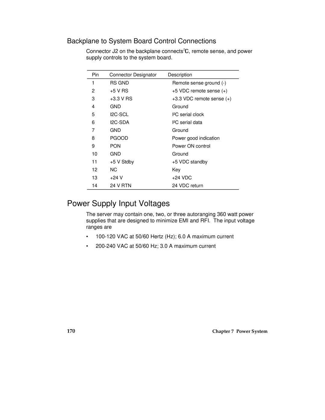
Connector J2 on the backplane connects I2C, remote sense, and power supply controls to the system board.
Pin | Connector Designator | Description |
1 | RS GND | Remote sense ground |
2 | +5 V RS | +5 VDC remote sense (+) |
3 | +3.3 V RS | +3.3 VDC remote sense (+) |
4 | GND | Ground |
5 | I²C serial clock | |
6 | I²C serial data | |
7 | GND | Ground |
8 | PGOOD | Power good indication |
9 | PON | Power ON control |
10 | GND | Ground |
11 | +5 V Stdby | +5 VDC standby |
12 | NC | Key |
13 | +24 V | +24 VDC |
14 | 24 V RTN | 24 VDC return |
|
|
|
Power Supply Input Voltages
The server may contain one, two, or three autoranging 360 watt power supplies that are designed to minimize EMI and RFI. The input voltage ranges are
∙
∙
170 | Chapter 7 Power System |
