Front Panel Connector
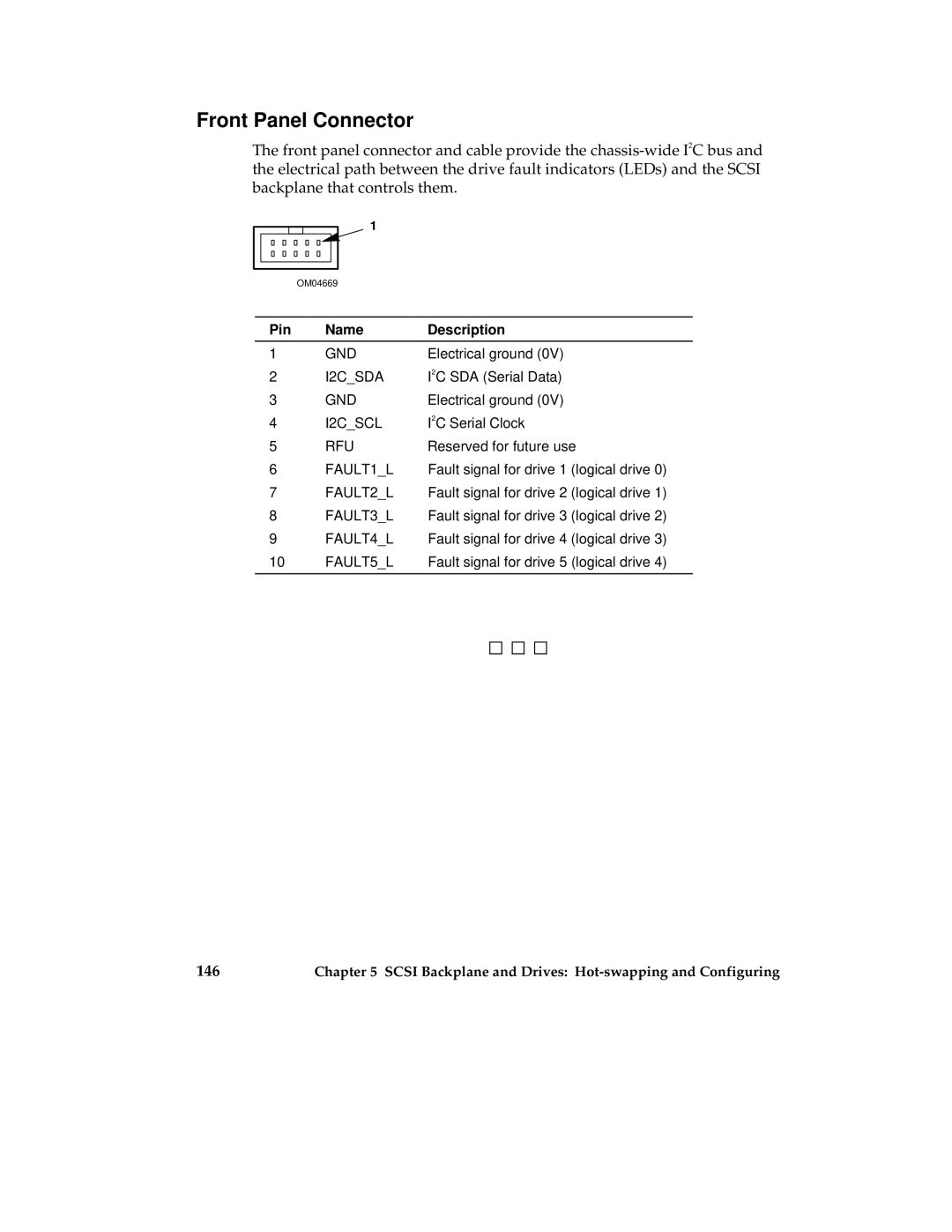
The front panel connector and cable provide the
1
OM04669
Pin | Name | Description |
1 | GND | Electrical ground (0V) |
2 | I2C_SDA | I2C SDA (Serial Data) |
3 | GND | Electrical ground (0V) |
4 | I2C_SCL | I2C Serial Clock |
5 | RFU | Reserved for future use |
6FAULT1_L Fault signal for drive 1 (logical drive 0)
7FAULT2_L Fault signal for drive 2 (logical drive 1)
8FAULT3_L Fault signal for drive 3 (logical drive 2)
9FAULT4_L Fault signal for drive 4 (logical drive 3)
10FAULT5_L Fault signal for drive 5 (logical drive 4)
146 | Chapter 5 SCSI Backplane and Drives: |