Zone 3 ConnectorsControls, LEDs and Connectors
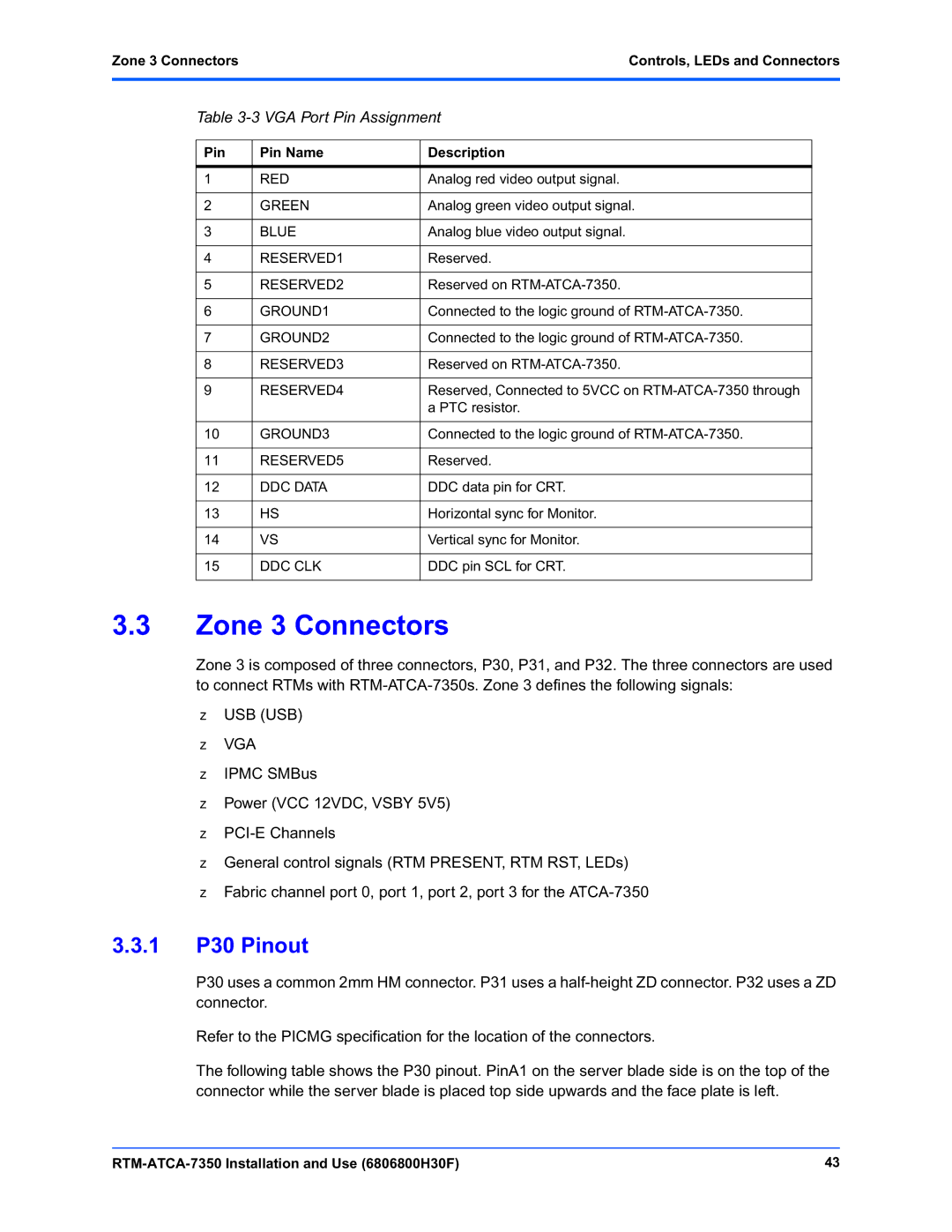
Table 3-3 VGA Port Pin Assignment
Pin | Pin Name | Description |
|
|
|
1 | RED | Analog red video output signal. |
|
|
|
2 | GREEN | Analog green video output signal. |
|
|
|
3 | BLUE | Analog blue video output signal. |
|
|
|
4 | RESERVED1 | Reserved. |
|
|
|
5 | RESERVED2 | Reserved on |
|
|
|
6 | GROUND1 | Connected to the logic ground of |
|
|
|
7 | GROUND2 | Connected to the logic ground of |
|
|
|
8 | RESERVED3 | Reserved on |
|
|
|
9 | RESERVED4 | Reserved, Connected to 5VCC on |
|
| a PTC resistor. |
|
|
|
10 | GROUND3 | Connected to the logic ground of |
|
|
|
11 | RESERVED5 | Reserved. |
|
|
|
12 | DDC DATA | DDC data pin for CRT. |
|
|
|
13 | HS | Horizontal sync for Monitor. |
|
|
|
14 | VS | Vertical sync for Monitor. |
|
|
|
15 | DDC CLK | DDC pin SCL for CRT. |
|
|
|
3.3Zone 3 Connectors
Zone 3 is composed of three connectors, P30, P31, and P32. The three connectors are used to connect RTMs with
zUSB (USB)
zVGA
zIPMC SMBus
zPower (VCC 12VDC, VSBY 5V5)
z
zGeneral control signals (RTM PRESENT, RTM RST, LEDs)
zFabric channel port 0, port 1, port 2, port 3 for the
3.3.1P30 Pinout
P30 uses a common 2mm HM connector. P31 uses a
Refer to the PICMG specification for the location of the connectors.
The following table shows the P30 pinout. PinA1 on the server blade side is on the top of the connector while the server blade is placed top side upwards and the face plate is left.
43 |
