Power Share Backplane Interconnections
Power Supply to Powershare Board Connections
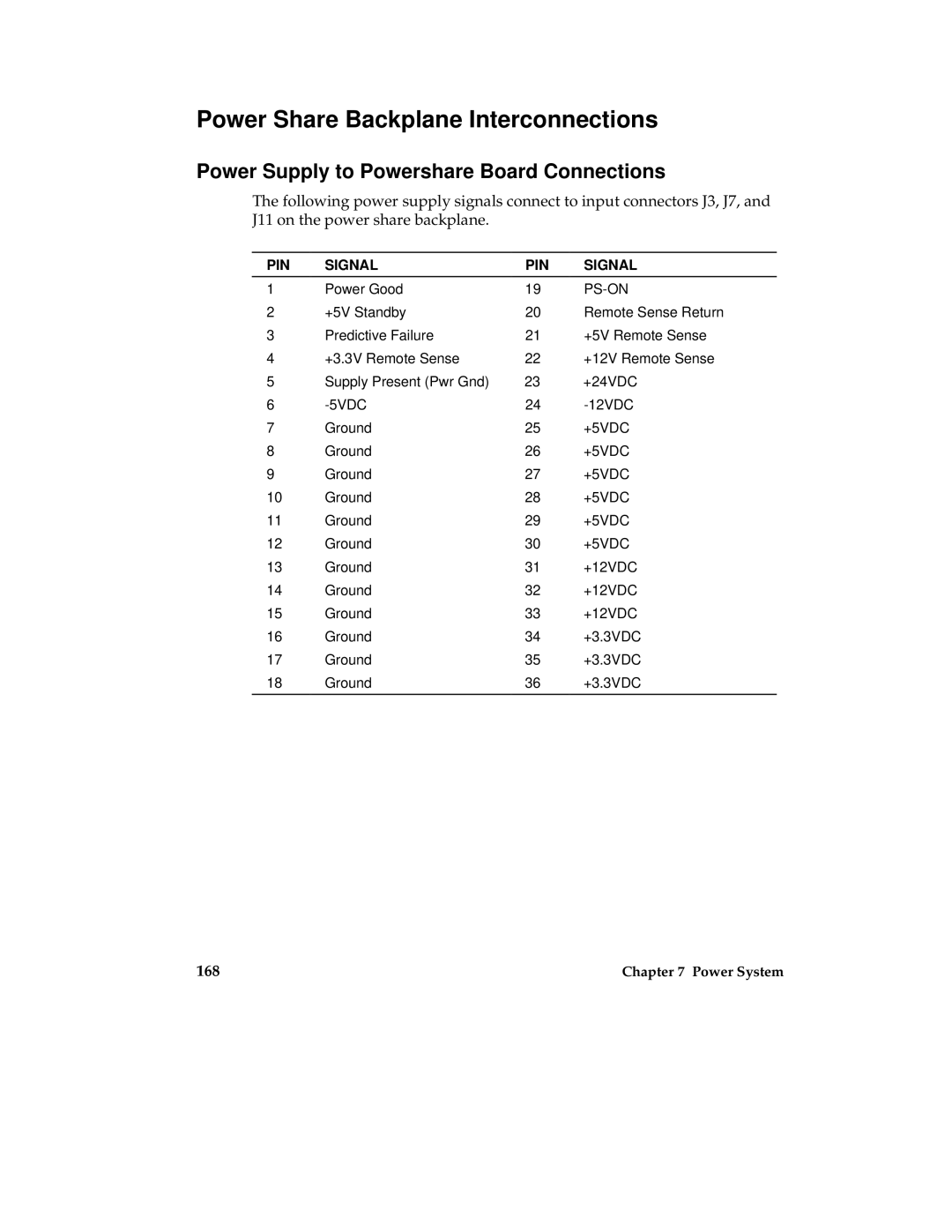
The following power supply signals connect to input connectors J3, J7, and J11 on the power share backplane.
PIN | SIGNAL | PIN | SIGNAL |
1 | Power Good | 19 |
|
2 | +5V Standby | 20 | Remote Sense Return |
3 | Predictive Failure | 21 | +5V Remote Sense |
4 | +3.3V Remote Sense | 22 | +12V Remote Sense |
5 | Supply Present (Pwr Gnd) | 23 | +24VDC |
6 | 24 | ||
7 | Ground | 25 | +5VDC |
8 | Ground | 26 | +5VDC |
9 | Ground | 27 | +5VDC |
10 | Ground | 28 | +5VDC |
11 | Ground | 29 | +5VDC |
12 | Ground | 30 | +5VDC |
13 | Ground | 31 | +12VDC |
14 | Ground | 32 | +12VDC |
15 | Ground | 33 | +12VDC |
16 | Ground | 34 | +3.3VDC |
17 | Ground | 35 | +3.3VDC |
18 | Ground | 36 | +3.3VDC |
|
|
|
|
168 | Chapter 7 Power System |