Backplane to System Board Power Interface
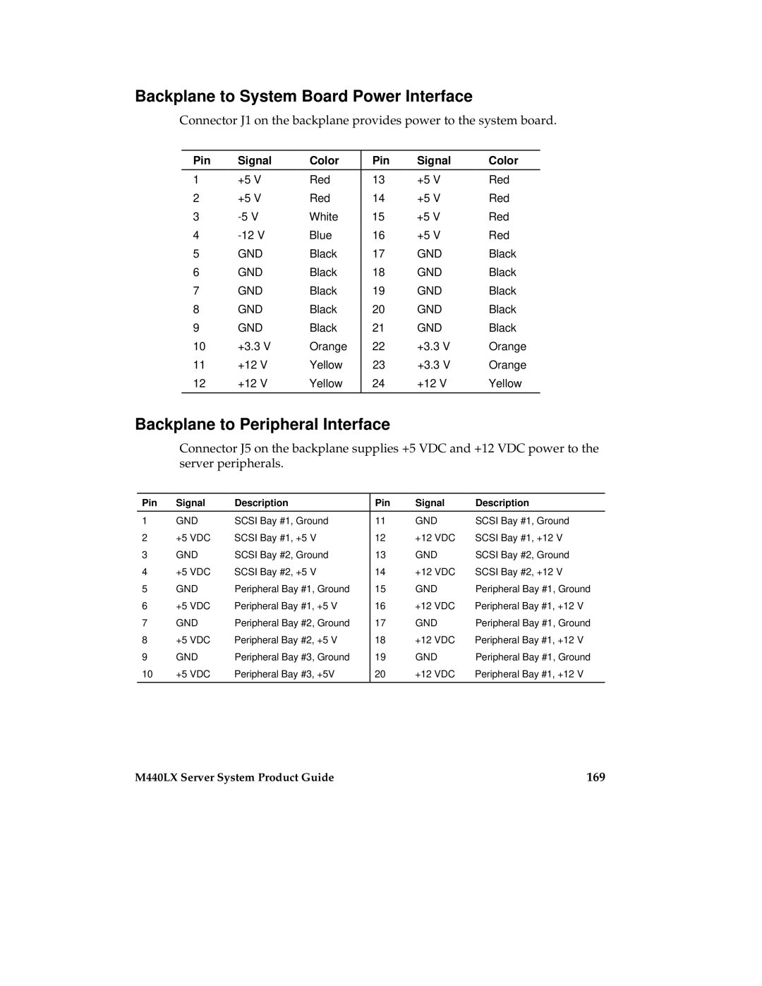
Connector J1 on the backplane provides power to the system board.
Pin | Signal | Color | Pin | Signal | Color |
|
|
|
|
|
|
1 | +5 V | Red | 13 | +5 V | Red |
2 | +5 V | Red | 14 | +5 V | Red |
3 | White | 15 | +5 V | Red | |
4 | Blue | 16 | +5 V | Red | |
5 | GND | Black | 17 | GND | Black |
6 | GND | Black | 18 | GND | Black |
7 | GND | Black | 19 | GND | Black |
8 | GND | Black | 20 | GND | Black |
9 | GND | Black | 21 | GND | Black |
10 | +3.3 V | Orange | 22 | +3.3 V | Orange |
11 | +12 V | Yellow | 23 | +3.3 V | Orange |
12 | +12 V | Yellow | 24 | +12 V | Yellow |
|
|
|
|
|
|
Backplane to Peripheral Interface
Connector J5 on the backplane supplies +5 VDC and +12 VDC power to the server peripherals.
Pin | Signal | Description | Pin | Signal | Description |
|
|
|
|
|
|
1 | GND | SCSI Bay #1, Ground | 11 | GND | SCSI Bay #1, Ground |
2 | +5 VDC | SCSI Bay #1, +5 V | 12 | +12 VDC | SCSI Bay #1, +12 V |
3 | GND | SCSI Bay #2, Ground | 13 | GND | SCSI Bay #2, Ground |
4 | +5 VDC | SCSI Bay #2, +5 V | 14 | +12 VDC | SCSI Bay #2, +12 V |
5 | GND | Peripheral Bay #1, Ground | 15 | GND | Peripheral Bay #1, Ground |
6 | +5 VDC | Peripheral Bay #1, +5 V | 16 | +12 VDC | Peripheral Bay #1, +12 V |
7 | GND | Peripheral Bay #2, Ground | 17 | GND | Peripheral Bay #1, Ground |
8 | +5 VDC | Peripheral Bay #2, +5 V | 18 | +12 VDC | Peripheral Bay #1, +12 V |
9 | GND | Peripheral Bay #3, Ground | 19 | GND | Peripheral Bay #1, Ground |
10 | +5 VDC | Peripheral Bay #3, +5V | 20 | +12 VDC | Peripheral Bay #1, +12 V |
|
|
|
|
|
|
M440LX Server System Product Guide | 169 |