Manuals
/
Intel
/
Marine Equipment
/
Life Jacket
Intel
MB440LX
manual
Lithium Back-up Battery
Models:
MB440LX
1
114
232
232
Download
232 pages
26.75 Kb
111
112
113
114
115
116
117
118
Specification
Install
Error codes
Pin Signal
Password
Power Supply Fault
Controls and Indicators
Administrator
Connecting Peripheral Devices
System Configuration Options
Page 114
Image 114
2
1
3
OM05791A
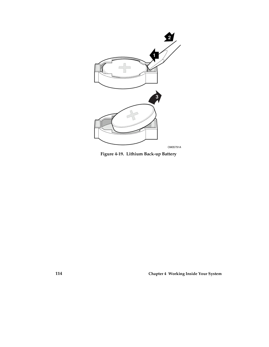
Figure
4-19.
Lithium
Back-up
Battery
114
Chapter 4 Working Inside Your System
Page 113
Page 115
Page 114
Image 114
Page 113
Page 115
Contents
Intel MB440LX System Installation Guide
Printed on Recycled paper
Safety Guidelines
Safety Guidelines
Preface
Notational Conventions
Your Chapter Title Goes Here
Contents
Installing The System
Configuring The System
Working Inside Your System
Scsi Backplane and Drives Hot-swapping Configuring
Power System
Server Resources
Ports and Connectors
System Board Jumpers
Solving Problems
Regulatory Specifications
Equipment Log
Tables
Figures
M440LX Server System Product Guide
Contents
Server Description
∙ One or two Pentium II processors
System Features
Feature Description
Feature Description
Chassis
Server
Back/Right Side View
Controls and Indicators
Front Panel
Peripherals
Controls and Indicators
Security with the System Configuration Utility SCU
Security with padlocks and alarm switches
Security with the Setup utility
System Security
Security Padlocks
Boot Sequence Control
Password Protection
Secure Boot Mode
Boot Without Keyboard
Diskette Write Protection
Power System
Server Cooling
Video Blanking
Peripheral Drive Bays
Inch User Accessible Diskette Drive Bay
Inch User Accessible Drive Bays
Inch Hot-docking Drive Bays
Onboard RAID
Server System Board
ISA Expansion Slots
PCI Expansion Slots
PCI Video Controller
Video Modes
Standard VGA Modes
Extended VGA Modes
Scsi Controllers
IDE Controller
Server Management
Baseboard Management Controller BMC does the following
Pentium II Processor
Memory Module
System Configuration Options
Base System Configuration
System Upgrade Options
Installing The System
Selecting a Site
Physical Specifications
Environmental Specifications
Installing the Pentium II Processor
Installing the Memory Module
After Unpacking the Server
Mouse
Connecting Peripheral Devices
Keyboard
Monitor
Server I/O Panel
Checking the Power Cords
Turning on Your Server
Power-on Self-Test
Power and Reset Buttons
Creating Installation Software Diskettes
Installing The System
Configuring The System
Configuration Utilities
Power-on Self-Test
When to Use the System Configuration Utility
How to start the SCU
System Board Settings Field Descriptions
Systems Group
Memory Subsystem Group
On-Board Disk Controllers
Onboard Communications Devices
Extended Memory Options
IDE Configuration Primary Master
Floppy Drive Subsystems Group
IDE Subsystem Group
IDE Drive Options Primary Slave
IDE Configuration Primary Slave
IDE Drive Options Primary Master
Standard CHS
KB and Mouse Subsystem Group
Multiboot Group
Boot Device Priority
Console Redirection
Security Subsystem
Administrative Password Option
User Password Option
Other Security Subsystem Options
Scsi ROM Bios Options Group
Management Subsystem Group
When to Run the Bios Setup Utility
Running the Setup Utility
Press
ESC
Main Menu
IDE Submenu
Keyboard Features Submenu
30/sec
Sec
Advanced Menu
DOS
PCI Configuration Submenu
Embedded Scsi Device Submenu
0040h
Integrated Peripherals Submenu
3F8
Normal
Primary
2F8
378
Secondary
Administrator
Security Menu
Password Submenu
Server Menu
System Management Submenu
Boot Menu
Console Redirection Submenu
9600
Boot Device Priority Submenu
Hard Drive Submenu
Exit Menu
Running the Scsi Utility
Using the Symbios Scsi Utility
Hot Keys
Press these keys
Installing Video Drivers
Installing Scsi Drivers
Configuring The System
Working Inside Your System
Preparation
Tools and Supplies You Need
Covers
Removing a Side Cover
Replacing a Side Cover
Side Covers
Removing the Top Cover
Replacing the Top Cover
Top Cover
Removing the Plastic Front Cover
Replacing the Plastic Front Cover
Plastic Front Cover
Removing the Snap-in Plastic Peripheral Bay Cover
Snap-in Plastic Peripheral Bay Cover
Replacing the Snap-in Plastic Peripheral Bay Cover
Board Set
Removing the Termination Board
Installing a Voltage Regulator Module
Removing a Termination Board
Installing a Voltage Regulator Module
Installing a Pentium II Processor
Installing a Pentium II Processor
Installing the Memory Module
Removing a Pentium II Processor
Installing the Memory Module
Installing the RPX Module
Removing the Memory Module
Installing the RPX Module
Removing the RPX Module
Add-in Boards
Installing an Add-in Board
10. Expansion Slot Cover
M440LX Server System Product Guide
11. Installing an ISA Add-in Board, Component-side Up
12. Installing a PCI Add-in Board, Component-side Down
101
Removing an Add-in Board
Diskette Drive
Removing the Diskette Drive
103
13. Removing the Diskette Drive
Installing a Diskette Drive
105
Inch Peripherals
Installing a 5.25-inch Peripheral Device
107
16. Removing the EMI Shield
17. Snap-in Plastic Slide Rails
109
18. Installing a 5.25-inch Peripheral Device
Removing a 5.25-inch Peripheral Device
111
Back-up Battery
Varning
Replacing the Back-up Battery
113
19. Lithium Back-up Battery
Replacing the Front Panel Board
Front Panel Board
Removing the Front Panel Board
115
20. Removing the Front Panel Board
Fans
Removing a Front Panel Fan
117
21. Front Panel Fans
22. Front Fan Assembly
119
Removing the Fan Below the Top Power Supply
Replacing a Front Panel Fan
23. Fan Below the Top Power Supply
121
24. Rear Fan Assembly
Replacing the Fan Below the Power Supply
123
Removing a Power Supply
Replacing a Power Supply
125
Power Share Backplane
Removing the Power Share Backplane
26. Removing the Power Share Backplane
127
27. Power Share Backplane Connectors
Installing the Power Share Backplane
129
Installing a Hot-docking Backplane
Scsi Hot-docking Backplane
Removing a Hot-docking Backplane
28. Removing a Hot-docking Backplane
131
132 Working Inside Your System
Hot-docking Bays
Scsi Backplane and Drives Hot-swapping and Configuring
Tools and Supplies You Need
133
Scsi Hard Disk Drive
Mounting a Scsi SCA Hard Disk Drive in a Plastic Carrier
135
Installing a Scsi SCA Hard Disk Drive in a Hot-docking Bay
Installing a Hard Disk Drive
137
Hot-swapping a Scsi SCA Hard Disk Drive
Configuration Options
139
Scsi ID Configuration Options
Internal/External INT/EXT Jumper J8
J10 Drive
Changing Scsi Device ID Addresses
141
Scsi Backplane
Pin Signal
Scsi Hot-docking Backplane Connectors
Wide/Fast Scsi 16-Bit Connector
143
Wide/Fast SCA2 Scsi 16-Bit Connectors
Power Connectors
Fan Connector
145
Front Panel Connector
Pin Name Description
Server Resources
147
Memory Module Resources
148 Server Resources
Memory Module
149
Extended Memory Region
Memory Regions
DOS Compatibility Region
Address Range hex Amount Function
Sample Dimm Size Combinations
ECC Memory
ECC Memory Banks
151
Installing DIMMs
152 Server Resources
Dimm Orientation
153
Properly Seated Dimm
Removing DIMMs
155
Removing ECC Memory DIMMs
Video Memory Dram
Installing the Video Memory Dram
System Board Resources
Removing the Video Memory Dram
U7C1
Addresses and Resources
159
Address Resource
160 Server Resources
Interrupts
161
Flash ROM
Configuration level Redundancy Number of supplies
Power System
Power System Configurations
163
Power System Voltages +3.3V +5V +12V
Output Power Connections
Power System Control Signals
Power Enable/Disable PON
Remote Sense Connections
VA Monitor Circuit
Power Good Circuit
Connectors +12
²C Communication Circuit
System Current Monitor
Power Supply Fault
Power Supply Presence Detect
167
Power Share Backplane Interconnections
Power Supply to Powershare Board Connections
Backplane to Peripheral Interface
Backplane to System Board Power Interface
Pin Signal Color
169
Power Supply Input Voltages
Pin Connector Designator Description
Backplane to System Board Control Connections
Power Supply Output Voltages
171
Server Current Usage
173
Current maximum at voltage levels
Device +3.3 +12
Calculating Power Usage
Total Combined Power Used by Your System
Total Combined Wattage
Worksheet for Calculating DC Power Usage
175
Current maximum at Voltage levels Device +12
Total Current
System Board Jumpers
177
Configuration Jumpers
System Board Jumpers
Chassis Intrusion Detection
Pins default Jumper Bold Description
Normal Boot
179
Fault Resilient Booting FRB
Updating the Bios
Flash Memory
CPU Speed
181
Boot Option
Recovering the Bios
Password
183
Beep Code Message
Cmos
Ports and Connectors
Signal States
185
System Board Layout
System Board Layout
System Board Connector Locations
187
Power Connector
Auxiliary Power Connector
I2C Connector
Control Panel Connector
Diskette Drive Port
189
Wide/Fast 16-Bit Scsi Connector
IDE Connector
191
Fan Connectors
Blower Connectors
Scsi Controller Activity LED Connector
Server Management Connector
Pin Signal Description
193
ISA Connectors
Pin Signal
PCI Connectors
195
Keyboard and Mouse Connectors
Mouse Keyboard Pin Signal
Parallel Port
197
VGA Video Port
Serial Ports
199
200 Ports and Connectors
Manually
Solving Problems
Resetting the Server
Programmed
Checklist
Initial System Startup
Running New Application Software
203
After the System Has Been Running Correctly
Additional Troubleshooting Procedures
Preparing the System for Diagnostic Testing
205
Monitoring Post
Verifying Proper Operation of Key System Lights
Confirming Loading of the Operating System
Specific Problems and Corrective Actions
Power Light Does Not Light
207
System Cooling Fans Do Not Rotate Properly
No Characters Appear on Screen
Characters Are Distorted or Incorrect
209
Incorrect or no Beep Codes
Diskette Drive Activity Light Does Not Light
Hard Disk Drive Activity Light Does Not Light
211
Problems With Application Software
Post Beep Codes
Error and Informational Messages
Beeps Error Message and Conditions
Post Beep Codes
Port-80 Codes
Post Codes and Countdown Codes
Normal Port-80 Codes
Port 80 Code Reason
215
216 Solving Problems
217
218 Solving Problems
Code Error message
Post Error Codes and Messages
Post Error Codes and Messages
219
220 Solving Problems
221
222 Solving Problems
223
224 Solving Problems
Declaration of the Manufacturer or Importer
Regulatory Specifications a
Safety Compliance
225
Electromagnetic Compatibility Notice USA
Electromagnetic Compatibility EMC
CE Mark
Europe EN55022
227
Electromagnetic Compatibility Notices International
English translation of the notice above
Equipment Log B
229
Equipment Log
Equipment Log
231
281885-001
Top
Page
Image
Contents