Step | Task (continued) |
5.Secure the chassis ground connection first:
a Remove one outer nut and one washer from each of the six studs. One nut should remain, tight on the stud. If the inner nut is loose,
b Locate the chassis ground connector studs on the PEM front panel (see Figure 16). The two rightmost studs are the ground connection.
c Install the grounding cable onto the ground studs. The grounding cable must comply with your local electrical codes in size and color (typically the color is green or green with yellow stripe).
NOTE: Grounding cables must be terminated only with a
d Replace the two washers and nuts on the studs.
e With a
f Connect the opposite end of the grounding cable to the nearest appropriate facility grounding post.
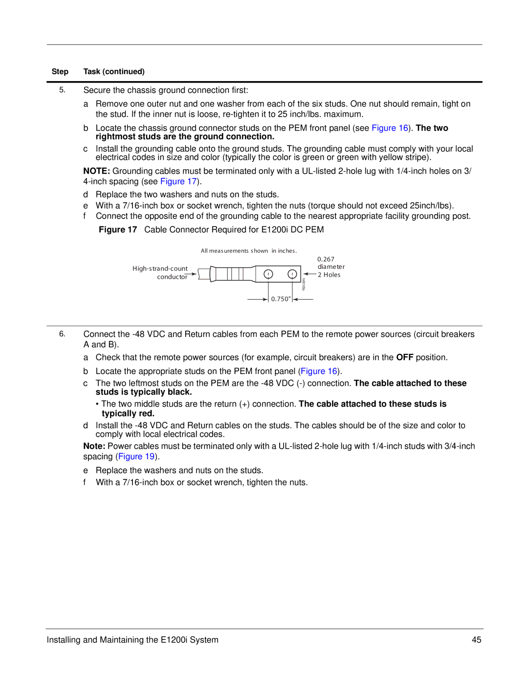
Figure 17 Cable Connector Required for E1200i DC PEM
All meas urements s hown in inches .
0.267 diameter 2 Holes
fn00105lp
0.750" ![]()
6.Connect the
a Check that the remote power sources (for example, circuit breakers) are in the OFF position. b Locate the appropriate studs on the PEM front panel (Figure 16).
c The two leftmost studs on the PEM are the
•The two middle studs are the return (+) connection. The cable attached to these studs is typically red.
dInstall the
Note: Power cables must be terminated only with a
eReplace the washers and nuts on the studs.
fWith a
Installing and Maintaining the E1200i System | 45 |