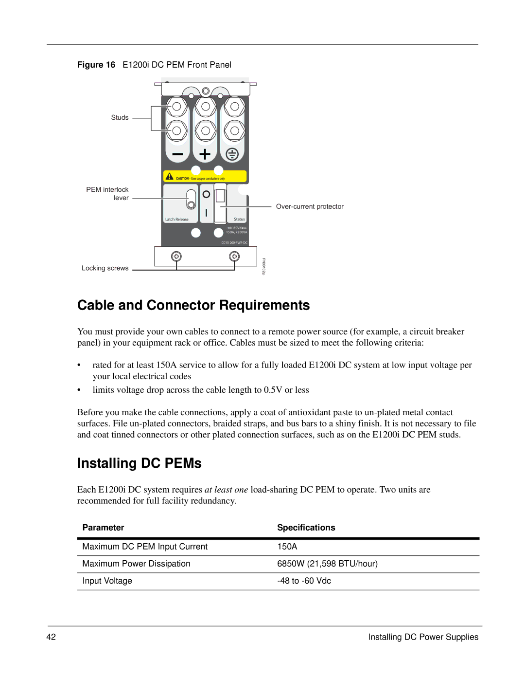
Figure 16 E1200i DC PEM Front Panel
Studs
PEM interlock lever
Locking screws
Latch Release
Status
FN00102lp
Cable and Connector Requirements
You must provide your own cables to connect to a remote power source (for example, a circuit breaker panel) in your equipment rack or office. Cables must be sized to meet the following criteria:
•rated for at least 150A service to allow for a fully loaded E1200i DC system at low input voltage per your local electrical codes
•limits voltage drop across the cable length to 0.5V or less
Before you make the cable connections, apply a coat of antioxidant paste to
Installing DC PEMs
Each E1200i DC system requires at least one
Parameter | Specifications |
|
|
Maximum DC PEM Input Current | 150A |
|
|
Maximum Power Dissipation | 6850W (21,598 BTU/hour) |
|
|
Input Voltage | |
|
|
42 | Installing DC Power Supplies |